
Characterization of second-order PMD in chirped fiber Bragg gratings - PowerPoint PPT Presentation
Title:
Characterization of second-order PMD in chirped fiber Bragg gratings
Description:
Characterization of second-order PMD in chirped fiber Bragg gratings ... CFBGs can be used for dispersion compensation in long haul fiber optic transmission systems ... – PowerPoint PPT presentation
Number of Views:162
Avg rating:3.0/5.0
Title: Characterization of second-order PMD in chirped fiber Bragg gratings
1
Characterization of second-order PMD in chirped
fiber Bragg gratings
C. Miscisin, R. Saperstein, K. Tetz, and Y.
Fainman
Background
Experimental Set-Up
- Chirped Fiber Bragg gratings (CFBGs) are useful
for Fiber Optic Communications and Optical Signal
Processing - CFBGs can be used for dispersion compensation in
long haul fiber optic transmission systems - Each wavelength is reflected at a different
location along the fiber canceling pulse spread
caused by chromatic dispersion - However, CFBGs suffer from severe 2nd order
polarization mode dispersion (PMD) - Each spectral component of light receives an
independent polarization rotation - If this 2nd order PMD can be characterized,
then it can be compensated.
Stokes Polarization Parameters
Poincaré Sphere
Mueller Matrix Formalism
- In 1852, Sir George Gabriel Stokes discovered
that the polarization behavior of light could be
represented in terms of real observables, he
developed a mathematical statement that could
represent fully, partially, and even un-polarized
light. - The Stokes polarization parameters can be
obtained by direct measurement of the time
averaged intensity of a lightwave that has passed
through a retarder and a polarizer in sequence.
- Around 1890 Henri Poincaré discovered that the
polarization ellipse could be represented on a
complex plane and that this plane could be
projected onto a sphere. - Six basis polarization states have Stokes
vectors which define the 3D axes of the Poincaré
sphere .
- In the early 1940s Hans Mueller became the
first person to describe polarizing components in
terms of matrices. - To derive a Mueller matrix for a polarization
altering device, for a single wavelength of
light, we have four equations and sixteen
unknowns. - Using four of the six basis polarization states
the calculation of a Mueller matrix is simplified.
I(0,0) I(90,0) I(0, 0) - I(90,0)
2I(45,0) I(0,0) I(90,0)
2I(45,90) I(0,0) I(90,0)
S0 Eox2 Eoy2 S1 Io Eox2 -
Eoy2 S2 2EoxEoycosd S3
2EoxEoysind
total intensity
amount of LHP or LVP
Incident Stokes vector
Amount of RCP or LCP
amount of linear L45 or L-45
(retardation, orientation of polarizer)
Experiment
Resultant Stokes vector
Mueller matrix describing a polarization altering
device
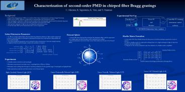
- A Mueller matrix is derived for each wavelength
- Polarization measurements were taken every ¼
wavelength from 1535nm to 1565nm - Polarization states resulting from the input of
each basis polarization for the specified range
of wavelengths are displayed below - Stokes polarization parameters and their
locations on the Poincaré sphere
Linear 45o Polarized Light (L45)
Linear Horizontally Polarized Light (LHP)
Linear Vertically Polarized Light (LVP)
Right Circularly Polarized Light (RCP)