
Future e /e- Linear Colliders CLIC and ILC - PowerPoint PPT Presentation
Title: Future e /e- Linear Colliders CLIC and ILC
1
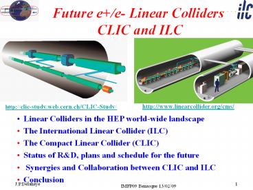
Future e/e- Linear Colliders CLIC and ILC
http//www.linearcollider.org/cms/
http//clic-study.web.cern.ch/CLIC-Study/
- Linear Colliders in the HEP world-wide landscape
- The International Linear Collider (ILC)
- The Compact Linear Collider (CLIC)
- Status of RD, plans and schedule for the future
- Synergies and Collaboration between CLIC and ILC
- Conclusion
2
Lepton and Hadron facilities complementary for
discovery and physics of new particles
Particle accelerators with colliding beams a long
standing success story in particles discoveries
and precision measurements
Energy (exponentially !) increasing with time a
factor 10 every 8 years!
- Hadron Colliders at the energy frontier as
discovery facilities - Lepton Colliders for precision physics
- LHC coming online from 2009
- Consensus for a future lepton linear collider to
complement LHC physics
3
Why e/e- collisions
- Hadron Colliders (p, ions)
- Protons are composite objects
- Only part of proton energy available
- Can only use pt conservation
- Huge QCD background
- Lepton Colliders
- Leptons are elementary particles
- Well defined initial state
- Momentum conservation eases decay product
analysis - Beam polarization
4
Why a linear collider ?
Circular colliders use magnets to bend particle
trajectories Their advantage is that they re-use
many times
5
LEP (27 km, 200 GeV e e-) _at_ CERN will probably
remain the largest circular lepton collider ever
built
6
A linear collider uses the accelerating cavities
only once
- Lots of them !
- Need a high accelerating gradient to reach the
wanted energy in a reasonable length (total
cost, cultural limit)
7
What matters in a linear collider ?
- Beam acceleration MWatts of beam power with
high gradient and - high efficiency
- Generation of small emittance Damping rings
- Conservation of small emittance Wake-fields,
alignment, stability - Extremely small beam sizes at Interaction Point
Beam delivery system, stability
8
The Linear Colliders father SLC _at_ SLAC
9
Broad range exploration of technologies (1988 -
2004)
500 GeV
TESLA SBLC JLC-S JLC-C JLC-X NLC VLEPP CLIC
Techno. Super Conduct Norm Cond. Norm. Cond. Norm. Cond. Norm. Cond. Norm. Cond. Norm. Cond. Two Beams
f GHz 1.3 3.0 2.8 5.7 11.4 11.4 14.0 30.0
L?1033 cm-2s-1 6 4 4 9 5 7 9 1-5
PbeamMW 16.5 7.3 1.3 4.3 3.2 4.2 2.4 1-4
PAC MW 164 139 118 209 114 103 57 100
gey?10-8m 100 50 4.8 4.8 4.8 5 7.5 15
synm 64 28 3 3 3 3.2 4 7.4
10
World-wide consensus about a Linear Collider as
the next HEP facility after LHC
- 2001 ICFA recommendation of a world-wide
collaboration to construct a high luminosity
e/e- Linear Collider with an energy range of 400
GeV/c upgradeable to at least 1 TeV - 2003 ILC-Technical Review Committee to assess
the technical status of the 15 years of RD on
various technologies and designs of Linear
Colliders - 2004 International Technology Recommendation
Panel selected the Super-Conducting RF technology
developed by the TESLA Collaboration for an
International Linear Collider (ILC) in the TeV
energy range - 2004 CERN council strong support for RD
addressing the feasibility of the CLIC technology
to possibly extend Linear Colliders into the
Multi-TeV energy range.
11
CERN Council Strategy Group(Lisbon July 2006)
12
Linear Collider Physics Goals(ICFA- ILCSC
parameters study)
- Ecm adjustable from 200 500 GeV
- Luminosity ? ?Ldt 500 fb-1 in 4 years
- Ability to scan between 200 and 500 GeV
- Energy stability and precision below 0.1
- Electron polarization of at least 80
- The machine must be upgradeable to 1 TeV
An ILC Reference Design Report has been published
which meets the required Physics goals
13
ILC Reference Design Reports
- Reference Design Report (4 volumes)
Physics at the ILC
Executive Summary
Detectors
Accelerator
14
ILC Reference Design Report (RDR)A world-wide
effort
700 Contributors from 84 Institutes
Reference Design Report http//www.slac.stanford
.edu/grp/ilc/positron/RDR-CD/ Companion
http//www.linearcollider.org/ilc_gatewayquantumun
iverse_draft.pdf
15
ILC _at_ 500 GeV
ILC web site http//www.linearcollider.org/cms/
Max. Center-of-mass energy 500 GeV
Peak Luminosity 2x1034 cm-2s-1
Beam Current 9.0 mA
Repetition rate 5 Hz
Average accelerating gradient 31.5 MV/m
Beam pulse length 0.95 ms
Total Site Length 31 km
Total AC Power Consumption 230 MW
31 km
16
Detector Concepts Report
17
ILC Value by Area Systems
International Costing for International
Project 6.4B ILC value units 13000
FTE-years ILC unit 1US (2007) 0.83 Euros
117 Yens http//media.linearcollider.org/estimatei
lcmachine.pdf
Main Cost Driver
Conventional Facilities Components
18
Main Linac RF Unit Overview
- 560 RF units each one composed of
- 1 Bouncer type modulator
- 1 Multibeam klystron (10 MW, 1.6 ms)
- 3 Cryostats (989 26 cavities)
- 1 Quadrupole at the center
Total of 1680 cryomodules and 14 560 SC RF
cavities
19
TESLA Module Results
20
Major issueLarge spread of achieved
accelerating gradients
ILC design
With the presently available technology
average 28 MV/m
Cost
increase 7
21
Combined Yield of Jlab and DESY Tests Reported
at TTC (Delhi, Oct. 2008), summarized by H.
Padamsee
23 tests, 11 cavities One Vender
48 Tests, 19 cavities ACCEL, AES, Zanon, Ichiro,
Jlab
50
Yield 50 at 35 MV/m being achieved by cavities
with a qualified vender !!
21
N. Walker - ILC08
22
Yield Curve 1st pass and 2nd passsummarized by
R. Geng
A8 I5 previously processed outside JLab w/
different facilities, excluded for analysis
- 10 cavities (5 qualified vendor 5 new vendors)
- A11 further re-cleaning with ultrasound HPR
22
N. Walker - ILC08
23
Ambitious SCRF test facilities in Asia, America
and Europe
KEK/JAPAN
24
Global SCRF Technology
N. Walker - ILC08
25
Global SCRF Technology
KEK, Japan
?
N. Walker - ILC08
26
Global SCRF Technology
FNAL, ANL
Cornell
?
KEK, Japan
?
JLAB
?
?
SLAC
?
N. Walker - ILC08
27
Global SCRF Technology
Cornell
DESY
?
KEK, Japan
?
FNAL, ANL
?
JLAB
LAL Saclay
?
?
SLAC
?
?
INFN Milan
?
Emerging SRF
N. Walker - ILC08
27
28
X-FEL at DESY a 10 ILC and a GEuros Test
Facility!
29
SRF Test Facilities
N. Walker - ILC08
29
30
Impressive RD and progress of SCRF cavities
performances
New preparation techniques
Derived From TESLA Collaboration
New material Large grains Higher perf Lower cost
New cavity shapes
31
Large Grain Material EP and BCP
D. Reschke et al.
32
ILC Polarized Electron Source
- Dual 140kV guns and dual polarized laser systems
- Energy compressor and spin rotator before DR
- Working on improved photocathode materials,laser
system and NC structures for 1 ms pulse
33
Positron Source
- Undulator-based positron source
- 150 meter undulator with K 0.9 l 1.2 cm
6mm aperture - Easy upgrade to produce polarized positrons
- Undulator located at 150 GeV in electron linac
- Eases operational issues when changing IP energy
- Two e production stations including 10 keep
alive
Schematic not updated for centralized injector
34
Damping Ring
Generation of ultra-low emittances ?x 8 ? 10-6
m-rad ?y 2 ? 10-8 m-rad Large number of
bunches Short Inj/Ext kicker risetime 6 km
circumference
35
KEK ATF - Layout
Cavity BPM
ATF2 Construction
Fast Kicker
Cavity Compton
DR-BPM upgrade
36
2.5 km Beam Delivery System with single
Interaction Region and 14 mrad crossing angle
Focusing to very small beam sizes Sx, Sy 640,
5.7 nm Final quadrupole magnets Superconducting
(QD0 in detector magnetic field) Crab Crossing
deflect head and tail oppositely for head
collisions
37
KEK ATF2 Layout
Final Focus System
Extraction line
Diagnostic
b mat- ching
38
ILC IR configuration stability
- Intratrain feedback within 1ms train
- No active mechanical stabilization of FD
- FD jitter tolerance about hundred nm
(old location)
Intratrain feedback kicker
39
Concept of IR hall with two detectors in Push-Pull
may be accessible during run
detector A
accessible during run
Platform for electronic and services (1088m).
Shielded (0.5m of concrete) from five sides.
Moves with detector. Also provide vibration
isolation.
40
(No Transcript)
41
ILC XFEL Timelines
GDE process
Reference Design Report (RDR)
Tech. Design Phase (TDP) 1
TDP 2
LHC physics
Ready for Project Submission
XFEL RD
XFEL preparatory engineering
XFEL civil construction
XFEL cryomodule production
FIRST BEAM
N. Walker - ILC08
42
- The ILC Plan and Schedule
(B.Barish/CERN/SPC 050913)
CLIC
Global Design Effort
Project
LHC Physics
Baseline configuration
Reference Design
Technical Design
ILC RD Program
Expression of Interest to Host
International Mgmt
2005 2006 2007 2008
2009 2010 2011
43
THE COMPACT LINEAR COLLIDER (CLIC) STUDY
- Aim develop technology to extend e-/e linear
colliders into the Multi-TeV energy range - http//clic-study.web.cern.ch/CLIC-Study/
- ECM energy range from ILC to LHC
- maximum reach and beyond gtECM 0.5- 3 TeV
- L gt few 1034 cm-2 with acceptable background and
energy spread ? ECM and L to be reviewed
when LHC physics results avail. - Affordable cost and power consumption
- Physics motivation
- http//clicphysics.web.cern.ch/CLICphysics/
- "Physics at the CLIC Multi-TeV Linear Collider
- by the CLIC Physics Working GroupCERN 2004-5
- Present goal
- Demonstrate all key feasibility issues and
document in a Conceptual Design Report by 2010
and possibly Technical Design Report by 2015
44
CLIC basic features
CLIC TUNNEL CROSS-SECTION
- High acceleration gradient gt 100 MV/m
- Compact collider total length lt 50 km at 3
TeV - Normal conducting acceleration structures at high
frequency - Novel Two-Beam Acceleration Scheme
- Cost effective, reliable, efficient
- Simple tunnel, no active elements
- Modular, easy energy upgrade in stages
4.5 m diameter
Drive beam - 95 A, 300 ns from 2.4 GeV to 240 MeV
12 GHz 140 MW
Main beam 1 A, 200 ns from 9 GeV to 1.5 TeV
45
326 klystrons 33 MW, 139 ms
drive beam accelerator 2.37 GeV, 1.0 GHz
1 km
delay loop
Drive Beam Generation Complex
CR2
decelerator, 24 sectors of 868 m
BDS 2.75 km
BDS 2.75 km
BC2
BC2
245m
IP1
245m
e- main linac , 12 GHz, 100 MV/m, 21.04 km
e main linac
TA R120m
TA R120m
48.3 km
CLIC overall layout 3 TeV
booster linac, 9 GeV, 2 GHz
Main Beam Generation Complex
BC1
e injector, 2.4 GeV
e- injector 2.4 GeV
e DR 365m
e- DR 365m
Main Drive Beam generation complexes not to
scale
46
326 klystrons 33 MW, 29 ms
drive beam accelerator 2.47 GeV, 1.0 GHz
1 km
delay loop
Drive Beam Generation Complex
CR2
decelerator, 5 sectors of 868 m
BDS 1.87 km
BDS 1.87 km
BC2
BC2
245m
IP1
245m
e- main linac , 12 GHz, 80 MV/m, 4.39 km
e main linac
TA R120m
TA R120m
13.0 km
CLIC overall layout 0.5 TeV
booster linac, 9 GeV, 2 GHz
Main Beam Generation Complex
BC1
e injector, 2.4 GeV
e- injector 2.4 GeV
e DR 365m
e- DR 365m
47
World-wide CLIC / CTF3 collaboration
http//clic-meeting.web.cern.ch/clic-meeting/CTF3_
Coordination_Mtg/Table_MoU.htm 24 members
representing 27 institutes involving 17 funding
agencies of 15 countries
27 collaborating institutes
University of Oslo (Norway) PSI
(Switzerland), Polytech. University of Catalonia
(Spain) RRCAT-Indore (India) Royal Holloway,
Univ. London, (UK) SLAC (USA) Uppsala University
(Sweden)
JINR (Russia) JLAB (USA) KEK (Japan) LAL/Orsay
(France) LAPP/ESIA (France) NCP
(Pakistan) North-West. Univ. Illinois (USA)
Ankara University (Turkey) BINP
(Russia) CERN CIEMAT (Spain) Cockcroft Institute
(UK) Gazi Universities (Turkey) IRFU/Saclay
(France)
Helsinki Institute of Physics (Finland) IAP
(Russia) IAP NASU (Ukraine) Instituto de Fisica
Corpuscular (Spain) INFN / LNF (Italy) J.Adams
Institute, (UK)
47
EPAC 2008 CLIC / CTF3 G.Geschonke, CERN
48
CLIC Chart 09
CLIC/ILC Collaboration
49
Tentative long-term CLIC scenarioShortest,
Success Oriented, Technically Limited Schedule
Technology evaluation and Physics assessment
based on LHC results for a possible decision on
Linear Collider with staged construction starting
with the lowest energy required by Physics
Conceptual Design Report (CDR)
Technical Design Report (TDR)
First Beam?
Project approval ?
50
CLIC major activities and milestones up to 2010
- Demonstrate feasibility of CLIC technology
- Address all feasibility issues
- Design of a linear Collider based on CLIC
technology - http//clic-study.web.cern.ch/CLIC-Study/Design.ht
m - Estimation of its cost (capital investment
operation) - CLIC Physics study and detector development
- http//clic-meeting.web.cern.ch/clic-meeting/CLIC_
Phy_Study_Website/default.html - Conceptual Design Report to be published in 2010
including - Physics, Accelerator and Detectors
- RD on critical issues and results of
feasibility study, - Preliminary performance and cost estimation
51
CLIC Parameters and upgrade scenariohttp//cdsweb
.cern.ch/record/1132079/files/CERN-OPEN-2008-021.p
df
4th phase 3 TeV luminosity upgrade 3 TeV
nominal parameters
2nd phase 500 GeV luminosity upgrade 500 GeV
nominal parameters
3rd phase 0.5 to 3 TeV energy upgrade 3 TeV
conservative parameters
1rst phase Initial operation 500 GeV
conservative parameters
52
Beam emittances at Damping Rings
53
Beam sizes at Collisions
54
CLIC main parameters http//cdsweb.cern.ch/record
/1132079?lnfr http//clic-meeting.web.cern.ch/
clic-meeting/clictable2007.html
Center-of-mass energy CLIC 500 G CLIC 500 G CLIC 3 TeV CLIC 3 TeV
Beam parameters Conservative Nominal Conservative Nominal
Accelerating structure 502 502 G G
Total (Peak 1) luminosity 0.9(0.6)1034 2.3(1.4)1034 1.5(0.73)1034 5.9(2.0)1034
Repetition rate (Hz) 50 50 50 50
Loaded accel. gradient MV/m 80 80 100 100
Main linac RF frequency GHz 12 12 12 12
Bunch charge109 6.8 6.8 3.72 3.72
Bunch separation (ns) 0.5 0.5 0.5 0.5
Beam pulse duration (ns) 177 177 156 156
Beam power/beam (MWatts) 4.9 4.9 14 14
Hor./vert. norm. emitt (10-6/10-9) 3/40 2.4/25 2.4/20 0.66/20
Hor/Vert FF focusing (mm) 10/0.4 8 / 0.1 8 / 0.3 8 / 0.1 8 / 0.3 4 / 0.07
Hor./vert. IP beam size (nm) 248 / 5.7 202 / 2.3 83 / 2.0 40 / 1.0
Hadronic events/crossing at IP 0.07 0.19 0.57 2.7
Coherent pairs at IP 10 100 5 107 3.8 108
BDS length (km) 1.87 1.87 2.75 2.75
Total site length km 13.0 13.0 48.3 48.3
Wall plug to beam transfert eff 7.5 7.5 6.8 6.8
Total power consumption MW 129.4 129.4 415 415
55
LC 500 GeV Main parameters
Center-of-mass energy ILC CLIC conserv. CLIC conserv. CLIC Nominal
Total (Peak 1) luminosity 2.0(1.5)1034 0.9(0.6)1034 0.9(0.6)1034 2.3(1.4)1034
Repetition rate (Hz) 5 50 50 50
Loaded accel. gradient MV/m 33.5 80 80 80
Main linac RF frequency GHz 1.3 (SC) 12 (NC) 12 (NC) 12 (NC)
Bunch charge109 20 6.8 6.8 6.8
Bunch separation ns 176 0.5 0.5 0.5
Beam pulse duration (ns) 1000 177 177 177
Beam power/linac (MWatts) 10.2 4.9 4.9 4.9
Hor./vert. norm. emitt (10-6/10-9) 10/40 3 / 40 2.4 / 25 2.4 / 25
Hor/Vert FF focusing (mm) 20/0.4 10/0.4 8/0.1 8/0.1
Hor./vert. IP beam size (nm) 640/5.7 248 / 5.7 202/ 2.3 202/ 2.3
Soft Hadronic event at IP 0.12 0.07 0.19 0.19
Coherent pairs/crossing at IP 10? 10 100 100
BDS length (km) 2.23 (1 TeV) 1.87 1.87 1.87
Total site length (km) 31 13.0 13.0 13.0
Wall plug to beam transfer eff. 9.4 7.5 7.5 7.5
Total power consumption MW 216 129.4 129.4 129.4
56
Strategy to address key issues
- Key issues common to all Linear Collider studies
independently of the chosen technology in close
collaboration with International Linear Collider
(ILC) study - The Accelerator Test Facility (ATF_at_KEK)
- European Laboratories in the frame of
- the Coordinated Accelerator Research in Europe
(CARE) and of a Design Study (EUROTeV) funded
by EU Programme (FP6) - The European Coordination of Accerator RD funded
by EU FP7 - Key issues specific to CLIC technology
- Focus of the CLIC study
- All R1 (feasibility) and R2 (design finalisation)
key issues addressed in test facilities CTF_at_CERN
57
CLIC critical issuesRD strategy and schedule
- Updated from the Technical Review Committee
(TRC) (2003) - Overall list available under
https//edms.cern.ch/document/918791 - Issues classified in three categories
- critical for CLIC design and technology
feasibility - Fully addressed by 2010 by specific RD with
results in Conceptual Design Report (CDR) with
Preliminary Performance Cost - critical for performance
- critical for cost
- Both being addressed now by specific RD to be
completed before 2015 with results in Technical
Design Report (TDR) with Consolidated Performance
Cost
58
CLIC feasibility issues
59
CLIC ILC common Test Facilities(identified in
red)
CLIC critical issues
60
Addressing all major CLIC technology key
issuesin CLIC Test Facility (CTF3)
Multi-lateral Collaboration of 27 volunteer
institutes organized as a Physics Detector
Collaboration
2005
2004
30 GHz stand and laser room 2004 - 2009
TL2 2007
CLEX 2007-2009
Combiner Ring 2006
Key issues
From 2005 Accelerating structures (bi-metallic)
Development Tests (R2.1)
2007- 2008 Drive beam generation scheme (R1.2)
2008- 2009 Damped accelerating structure with
nominal parameters (R1.1)
ON/OFF Power Extraction Structure (R1.3)
Drive beam stability bench marking
(R2.2) CLIC sub-unit
(R2.3)
61
CTF3 Continuous 0peration (10months/year) HW
Beam Commisioning and RF power production for
structure tests
TL1
- Demonstrate Drive Beam generation (fully loaded
acceleration, beam intensity and bunch frequency
multiplication x8) - Demonstrate RF Power Production and test Power
Structures - Demonstrate Two Beam Acceleration and test
Accelerating Structures
2005
2004
DL
CR
TL2
Beam up tohere
CLEX
Jan 2007
62
CTF3 Collaboration
CTF3 Collaborations
INFN-LNF CIEMAT BINP LURE CERN NWU LAPP Uppsala
INFN-LNF CERN
INFN-LNF CERN
RRCAT TSL CERN
CERN NWU PSI Uppsala
IAP
CEA-DAPNIA CERN LAL
CERN LAL SLAC
Uppsala CERN
CIEMAT UPC IFIC CERN
R.Corsini
62
EPAC 2008 CLIC / CTF3 G.Geschonke, CERN
63
Drive beam generation with full beam-loading
acceleration in CTF3 linac
- Measured RF-to-beam efficiency 95.3
- Theory 96( 4 ohmic losses)
64
CTF3 HW Beam Commissioning
Phase coding
Intensity and frequency multiplication by 2 in
Delay Loop
Installation complete apart from TBL
Intensity and frequency multiplication by 4 in
Combiner Ring
Beam all the way through CLEX
65
CLIC Experimental Area (CLEX)
- Two Beam Test Stand to study probe beam
acceleration with high fields at high frequency
and the feasibility of Two Beam modules - - Test beam line (TBL) to study RF power
production (1.5 TW at 12 GHz) and drive beam
decelerator dynamics, stability losses
Equipment installed (except TBL), Beam from June
2008
65
EPAC 2008 CLIC / CTF3 G.Geschonke, CERN
66
Power Extraction Structure test (PETS) in CTF3
PETS installation in tank successful
(collaboration with Pakistan NPC
Islamabad) PETS installation in CLEX under way
66
67
Nominal CLIC Structure Performance demonstrated
A shining example of fruitful collaboration
T18_VG2.4_disk Designed at CERN, (without
damping) Built at KEK,
RF Tested at SLAC
Improvement by RF conditionning
Frequency 11.424 GHz
Cells 182 matching cells
Filling Time 36 ns
Length active acceleration 18 cm
Iris Dia. a/? 0.1550.10
Group Velocity vg/c 2.6-1.0
Phase Advace Per Cell 2p/3
Power for ltEagt100MV/m 55.5 MW
Unloaded Ea(out)/Ea(in) 1.55
Es/Ea 2
CLIC nominal
68
The path to the CLIC full-structure feasibility
demonstration Move from achieved result with
simplified structure to fully equipped, higher
efficiency structure
TD18
Supporting tests Quadrant fabrication CD10
Choke mode CD10
Add damping
Move to design iris range
Move to design iris range and add damping
CLIC_G with damping, full prototype
T18 tested to 105 MV/m, 230 ns, 2x10⁻⁷/(mxpulse)
Add damping
Move to design iris range
Supporting tests C10 series T23
CLIC_G undamped
Today
late 2009
Mid 2009
69
MASTER SCHEDULE (1/2)
04.12.2008
69
70
SLAC/ NLCTA Layout
- In the accelerator housing
- 2 x 2.5m slots for structures
- Shield Enclosure suitable up to 1 GeV
- For operation
- Can run 24/7 using automated controls
- 3 x RF stations
- 2 x pulse compressors (240ns - 300MW max), driven
each by 2 x 50MW X-band klystrons - 1 x pulse compressors (400ns 300MW /200ns
500MW variable), driven by 2 x 50MW X-band
klystrons. - 1 x Injector 65MeV, 0.3 nC / bunch
(Gain 3.1)
71
KEK / NEXTEF - Layout
- Presently,
- Two klystrons with a power combiner.
- Max. 120MW/300ns, Typical. 100MW/300ns at
comb.-out - 70MW/300ns at struc.-in
- Hoping to implement in 2010 (or later)
- Pulse compression to make power of 150MW
available.
72
12 GHz Klystron based RF power sourceX-b
Structure Test-Stand at CERN (and later CEA)X-b
Structure Operation at PSI and Trieste
12 GHz Klystron
Hybrid
50 mm vac. port
PC
? Klystron gallery Bldg. 2013 CTF2 ?
Structure test assembly
5 Klystrons 12 GHz 50 MWatts being developed by
SLAC
Analysis
RF load
73
X-Band structures for Linac based X-FEL at PSI
and ELETTRA/TRIESTE
74
CArbon BOoster Therapy in Oncology(CABOTO by
TERA foundation)
TERA
SC cyclotron
12 GHz NC Linac (power efficiency) CLIC/TERA
Collaboration
74
75
CLIC Two Beam Module
Main Beam
Transfer lines
20760 modules (2 meters long) 71460 power
production structures PETS (drive beam) 143010
accelerating structures (main beam)
Drive Beam
Main Beam
75
EPAC 2008 CLIC / CTF3 G.Geschonke, CERN
76
Two Beam Module tests in CTF3/CLEX
Two Beam Test Stand Contribution of Swedish
Collaboration Uppsala Univ. Design and
integration of different sub-systems, i.e. to
simultaneously satisfy requirements of highest
possible gradient, power handling, tight
mechanical tolerances and heavy HOM damping
76
04.12.2008
77
Tunnel integration
DB turn-around
DB dump
UTRA cavern
Standard tunnel with modules
77
04.12.2008
78
Longitudinal section of a laser straight Linear
Collider on CERN site
IP under CERN Prevessin site Phase 1 0.5 TeV
extension 13 km Phase 2 3 TeV extension 48.5 km
CERN site Prevessin
Detectors and Interaction Point
0.5TeV 13 Km
3 TeV 48.5 Km
79
The CLIC Injector complex in 2008
? 30 m
? 30 m
e- Main Linac
e Main Linac
e- BC2
e BC2
12 GHz
12 GHz
9 GeV
48 km
3 TeV Base line configuration Unpolarised
positrons
4 GHz
Booster Linac 6.6 GeV
473 m
e BC1
e- BC1
2.424 GeV 365 m
4 GHz
4 GHz
2.424 GeV 365 m
e DR
e- DR
e- PDR
e PDR
2.424 GeV
2.424 GeV
365 m
365 m
Injector Linac 2.2 GeV
2 GHz
228 m
e-/g Target
g/e Target
Laser
Primary beam Linac for e- 5 GeV
Pre-injector Linac for e- 200 MeV
Pre-injector Linac for e 200 MeV
DC gun Polarized e-
2 GHz
e- gun
2 GHz
2 GHz
AMD
80
The CLIC Injector complex (Compton)
e- Main Linac
e Main Linac
e- BC2
e BC2
12 GHz
12 GHz
9 GeV
48 km
3 TeV Laser Compton ring configurat. Polarised
positrons
Booster Linac 6.6 GeV
4 GHz
e BC1
e- BC1
2.424 GeV
4 GHz
2.424 GeV
4 GHz
e DR
e- DR
e PDR and Accumulator ring
2.424 GeV
e- PDR
2.424 GeV
Injector Linac 2.2 GeV
2 GHz
RF gun
e- Drive Linac 1.3 GeV
Compton ring
Laser
Pre-injector Linac for e- 200 MeV
Pre-injector Linac for e 200 MeV
2 GHz
DC gun Polarized e-
g
e Target
Stacking cavity
Laser
2 GHz
2 GHz
81
Damping ring design
PARAMETER NLC CLIC (3TeV)
bunch population (109) 7.5 4.1
bunch spacing ns 1.4 0.5
number of bunches/train 192 316
number of trains 3 1
Repetition rate Hz 120 50
Extracted hor. normalized emittance nm 2370 lt550
Extracted ver. normalized emittance nm lt30 lt5
Extracted long. normalized emittance keV.m 10.9 lt5
Injected hor. normalized emittance µm 150 63
Injected ver. normalized emittance µm 150 1.5
Injected long. normalized emittance keV.m 13.18 1240
- Present CLIC DR design for 3TeV achieves goals
for transverse emittances with a 20-30 margin
(380nm horizontal and 4.1nm vertical) - Conservative DR output emittances (2.4µm
horizontal, 10nm vertical) for CLIC _at_ 500GeV
scaled from operational or approved light source
projects (NSLSII, SLS) - Route to lower emittances to be defined
82
CLIC damping rings
- Two 365.2m long rings of racetrack shape _at_
2.424GeV - Arcs filled with TME cells and straights with
2m-long superconducting damping wigglers (2.5T,
5cm period) - Output emittance strongly dominated by IBS
- Issues to be addressed
- Lattice optimization (magnet design, non-linear
dynamics) - Superconducting wiggler design progress
(NbTi/Nb3Sn, radiation absorption) - Collective effects (e- cloud, IBS)
- RF system considerations
- ILC/CLIC DR common issues
- Pre-damping ring design (positron stacking)
M. Korostelev, PhD thesis, EPFL 2006
83
Beam emittance preservation Beam Dynamics,
alignment and stability
- Emittance blow-up from Damping Ring to BDS
limited - in Horizontal to 30 from 500 nrad
- in Vertical to 300 from 5 nrad
Magnet Horiz. Vert.
Linac (2600 quads) 14nm 1.3 nm
Final Focus (2quads) 4 nm .15 to1 nm
Pre-alignment precision 15 microns Beam based
alignement 5-10 microns Stability requirements
(gt 4 Hz)
CLIC tolerances
Need active damping of vibrations
Achieved stability on CERN vibration test stand
Test made in noisy environment, active damping
reduced vibrations by a factor about 20, to rms
residual amplitudes of Vert. 0.9 ? 0.1 nm 1.3 ?
0.2 nm with cooling water Horiz. 0.4 ? 0.1 nm
84
(No Transcript)
85
CLIC physics/detector studies have restarted
In preparation for CLIC Conceptual Design Report
(CDR) by 2010 In collaboration with ILC detector
community
3TeV ee- ? WW- ? qqqq
86
A necessary and beneficial CLIC /ILC
Collaboration
- http//clic-study.web.cern.ch/CLIC-Study/CLIC_ILC_
Collab_Mtg/Index.htm - Focusing on subjects with strong synergy between
CLIC ILC - making the best use of the available resources
- adopting systems as similar as possible
- identifying and understanding the differences due
to technology and energy (technical, cost.) - developing common knowledge of both designs and
technologies on status, advantages, issues and
prospects for the best use of future HEP - preparing together by the Linear Collider
Community made up of CLIC ILC experts - the future evaluation of the two technologies
- proposal(s) best adapted to the (future) HEP
requirements
87
CLIC and ILC layouts
ILC _at_ 500 GeV
88
Subjects with strong synergyWorking Groups
Conveners
CLIC ILC
Physics Detectors L.Linssen, D.Schlatter F.Richard, S.Yamada
Beam Delivery System (BDS) Machine Detector Interface (MDI) D.Schulte, R.Tomas Garcia E.Tsesmelis B.Parker, A.Seriy
Civil Engineering Conventional Facilities C.Hauviller, J.Osborne. J.Osborne, V.Kuchler
Positron Generation (new) L.Rinolfi J.Clarke
Damping Rings (new) Y.Papaphilipou M.Palmer
Beam Dynamics D.Schulte A.Latina, K.Kubo, N.Walker
Cost Schedule H.Braun (P.Lebrun), K.Foraz, G.Riddone J.Carwardine, P.Garbincius, T.Shidara
89
Nature Editorial
- (November 27, 2008)
- Given this financial uncertainty, it is
important that the high-energy physics community
does all it can to reduce any internal divisions
and to strengthen its external coherence. That is
why a new collaboration over what should come
after the LHC is to be greeted with enthusiasm. - The potential for destructive rivalry was real.
Yet late last month, leaders of the two efforts
formally agreed to collaborate as much as is
practicable. - The two rivals are closer than they have ever
been, and yet research and development on the two
underlying accelerator technologies will continue
apace with a healthy spirit of competition. - The result is that the ILC and CLIC are setting
an example that other large scientific endeavours
would do well to emulate.
90
Conclusion
- World wide consensus on Linear Colliders favored
facility to complement the LHC in the future. - ILC based on pretty mature SCRF technology
derived from TESLA Collaboration for a Linear
Collider in the TeV range. - Conceptual Design Report including cost
available, Technical Design Report by 2012 - RD to further improve performances and reduce
cost - Taking advantage of strong synergy with X-FEL
(industrialisation) - To be ready to be built as soon as interest for
Physics in the TeV range confirmed by LHC Physics
results and resources available - CLIC technology based on novel TBA scheme to
further extend energy reach of Linear Colliders
into the Multi-TeV range - Promising performances with possible substantial
cost savings - Novel scheme with challenging technology with
feasibility to be demonstrated in CTF3 and
published in Conceptual Design Report including
preliminary performances and cost by 2010 - Technical Design with consolidated design and
cost by 2015 - CLIC/ILC Competitive-Collaboration preparing
together proposal of the most appropriate
facility and technology based on Physics results
when available from the LHC in 2010-12 - Spanish contribution to present LC related RD
warmly appreciated and participation to the
future LC facility construction operation in a
world-wide project strongly welcome.
91
Spares
92
Relative cost of Linear Colliders
93
CLIC Machine installation
3 TeV
3 additional years
500 GeV
7 years ready for HW commisioning
Transport
Interconnections
CLIC08 Workshop - Katy Foraz
16 October 2008
94
CLIC Performance and Cost optimization
Luminosity / power
CLIC Old Parameters Accelerating field 150
MV/m RF frequency 30 GHz
CLIC New parameters Accelerating field 100
MV/m RF frequency 12 GHz
Total cost (a.u.)
A. Grudiev et al. EPAC 06
95
CTF3 RD issues
Adressed ongoing - next
recombination x 4
recombination x 2
bunch length control
bunch compression
fully loaded acceleration
PETS on-off
structures 12 GHz
phase-coding
deceleration stability
two-beam acceleration
structures 30 GHz
96
CTF3 High-Power test results 30 GHz
Breakdown Rate not compatible with LC operation
97
CTF3 High-Power test results 30 GHz
- Acceptable Breakdown Rate in linear collider
operation not higher than 10-6 - Reduction of accelerating field by about 30 MV/m
for low BR with Co
CLIC operational goal
J.A. Rodriguez et al. FROBC01
98
(No Transcript)
99
Test Beam Line TBL
- High energy-spread beam transport
- decelerate to 50 beam energy
- Drive Beam stability
- Stability of RF power extraction
- total power in 16 PETS 2.5 GW
- Alignment procedures
PETS design
5 MV/m deceleration (35 A) 165 MV output Power
PETS development CIEMAT BPM IFIC Valencia
and UPC Barcelona
2 standard cells, 16 total
99
EPAC 2008 CLIC / CTF3 G.Geschonke, CERN
100
TBL integration into CLEX
101
Design and construction/tests of 12 GHz
accelerating structuresCollaboration CLIC TERA
101
Recommended
CrystalGraphics Presentations


