
WHITEFIELD EQUIPMENTS PVT' LTD' - PowerPoint PPT Presentation
1 / 17
Title:
WHITEFIELD EQUIPMENTS PVT' LTD'
Description:
Two big insulated doors of size 2500mm X 4300mm are provided on the front of ... Heat exchanger is of finned tube type and is capable of generating heat upto 130 ... – PowerPoint PPT presentation
Number of Views:100
Avg rating:3.0/5.0
Title: WHITEFIELD EQUIPMENTS PVT' LTD'
1
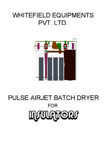
WHITEFIELD EQUIPMENTS PVT. LTD.
- PULSE AIRJET BATCH DRYER
- FOR
- INSULATORS
2
MAINTANANCE CUM OPERATION MANUAL
- EQUIPMENT
- PULSE AIRJET BATCH DRYER
- MODEL
- 01-21-SERIES TYPE DM-4
- SIZE
- 11200Lx6600Wx4200Ht
- CAPACITY
- 32MT PER CHARGE
- CUSTOMER
- INSULATORS AND ELECTRICALS COMPANY, MANDIDEEP,
MP.(NEW PLANT) - DRYER NUMBER
- D-7, D8 D-9
3
EQUIPMENT DETAILS
- The Pulse Air-jet batch dryer manufactured by
WEPL is a drying chamber fabricated out of Mild
Steel structurals and Insulated panels made of
CRCA sheet and Aluminium Sheets with slabs of
rockwool sandwitched between these sheets. This
chamber construction is very rugged and provides
good insulation. Moreover as aluminium is a good
conductor of heat cooling of the chamber is also
very fast which helps in making the dryer
available for loading within a few hours of
completion of the cycle unlike conventional
cement walled dryers which take a long time to
cool after each cycle. - The dryer is provided with heat exchangers and a
blower along with necessary ductings to heat the
chamber and to recirculate the hot air. - The dryer is also provided with a PULSE AIRJET
AIR CIRCULATION UNIT (ACU) for circulating the
air inside the chambers and works on Pulse airjet
or Intermittent flow principle which is
considered to be one of the best drying method
for insulators globally. - The front side of dryer consists of two large
doors and a LIFT AND SHIFT type door lifting
unit to facilitate easy loading and unloading of
wares using either forklift trucks or pallet
trucks. - One motorised threeway valve and two dampers with
motorised actuators are provided to contorl the
temperature and humidity inside the dryer. These
valves and Actuators can be connected to a PID or
PLC controller to run the dryer using the desired
pre programmed cycle.
4
PARTS LIST
- 1 ) CHAMBER
- 1.0) INSULATED CHAMBER
- 1.1)INSULATED PANELS
- 1.2)LOCKING CHANNELS
- 1.3)DOORS
- 1.4)INSPECTION DOORS
- 2)DUCTINGS
- 2.1)MAIN DUCT
- 2.2)SUCTION DUCT
- 2.3)DISCHARGE DUCT
- 3)HEAT EXCHANGER
- 3.1)HEAT EXCHANGER MS
- 3.2)HEAT EXCHANGER-SS
- 3.3)RADIATOR CHAMBER
- 3.4)CHAMBER BACK COVER
5
- 4)DRIVE UNITS
- 5)MOTORS
- 5.1)5 HP MOTOR
- 5.2)0.25HP GEARMOTOR
- 5.3)10 HP MOTOR
- 6)BLOWER
- 7)DOOR LIFTING UNIT
- 7.1)DOOR LIFTING UNT WHEEL
- 7.2)HYDRAULICS FOR LIFTING
- 8)MOTORISED THREE WAY VALVE
- 9)DAMPER
6
- 7)DOOR LIFTING UNIT
- 7.1)DOOR LIFTING UNT WHEEL
- 7.2)HYDRAULICS FOR LIFTING
- 8)MOTORISED THREE WAY VALVE
- 9)DAMPER
- 9.1)ACTUATOR
- 9.2)SERVO CONTROLLER
- 10)AIR CIRCULATION UNITS
- 10.1)ACU
- 10.2)CASING
- 10.3)AXIAL FAN
7
DETAILS
- 1 ) CHAMBER
- The size of the chamber is 11200mm Length X
6600mm width X 4200mm Ht. - 1.0) INSULATED CHAMBER
- The insulated chamber is constructed using mild
steel channels and insulated panels. The chamber
comes in a dismantled condition and is assembled
at site using nuts and bolts. - 1.1)INSULATED PANELS
- Insulated panels are panels made using aluminium
sheets,crca sheets and rockwool slabs of density
48kg/sqm and 75mmthk.The aluminium side will be
inside the dryer to help avoid corrosion. - 1.2)LOCKING CHANNELS
- Locking channels are channels formed out of
aluminium sheets and is used to cover the gap
betwwen two panels. They are very important as
they help in retaining heat inside the dryer. - 1.3)DOORS
- Two big insulated doors of size 2500mm X 4300mm
are provided on the front of dryer to facilitate
loading and unloading of wares. The doors are
operated using the door lifting unit.(ref 7) - 1.4)INSPECTION DOORS
- An insulated inspection door of size 2000mm X
1000mm is provided between two main doors. This
insulated door is hinged and can be opened to
remove samples in between the drying cycle. - 1.5)DOOR SEALING
- All the doors are seated on door frames using
asbestos tape to provide good sealing and
ensuring no heat loss is taking place.
8
- 2)DUCTINGS
- Ductings are fabricated out of crca sheets and
are either galvanised or painted with heat
resistant paint. They are used for circulating
hot air in the chamber. - 2.1)MAIN DUCT
- Main duct is the duct visible inside the dryer
with branches projecting to all the ACU cones.
This duct delivers air from the blower to the
chamber - 2.2)DISCHARGE DUCT
- Discharge duct connects the dryer and the blower.
- 2.3)SUCTION DUCT
- Suction duct is used to suck fresh air from
atmosphere and also to suck the hot air from the
chamber for recirculation. One damper ie fresh
air damper is mounted on this duct and the duct
is also connected to the blower. - 2.4)BEND DUCT
- Connects suction ducts to blower.
- 2.5)TRANSITION DUCTS
- Connects radiator chamber to discharge duct.
9
- 3)HEAT EXCHANGER
- Heat exchanger is of finned tube type and is
capable of generating heat upto 130 deg celsius
inside the drying chamber. The input required to
the heat exchanger is thermic fluid at 250 deg
celsius. - 3.1)HEAT EXCHANGER MS
- Two bundles of 36 tubes heat exchanger is fixed
to the radiator chamber. - 3.2)HEAT EXCHANGER-SS
- One bundle of 36 tubes heat exchanger is fixed to
the radiator chamber - 3.3)RADIATOR CHAMBER
- All the radiators are fixed on this insulated
chamber which is connected to the blower and
dryer using ductings. - 3.4)CHAMBER BACK COVER
- This cover is bolted on the back side of the
radiator and is used for removing radiators for
maintanance prposes.
10
- 4)DRIVE UNITS
- Drive units are special machine assemblies with
two concentric shafts rotating in radially
opposite directions.One shaft is connected to an
axial fan and and is rotated at RPM upto1400
using a 5hp motor coupled to the shaft and other
shaft is connected to the ACU which is rotated at
1 RPM using a geared motor . - 5)MOTORS
- 5.1)5 HP MOTOR
- This motor is connected to the axial fan using a
love joy coupling of size 3dia. The motor is a
3phase 4 pole squirrelcage induction motor of
SEIMENS or equivqlent make. - 5.2)0.25HP GEARMOTOR
- This is a gearbox of model 43.1KH,make ROTOFLEX
coupled with a 0.25hp SEIMENS or equivalent make
motor.The gear box is with two stage grease
filled gearboxes and the output RPM is 3 RPM. - 5.3)10 HP MOTOR
- This motor is connected to the blower .The motor
is a 3phase 4 pole squirrelcage induction motor
of SEIMENS or equivqlent make. - 6)BLOWER
- The blower is of APCON - Bangalore make and
capacity is 12000CMH and working condition is
from 30 deg celsius to 130 deg celsius.
- Bearings for drive Unit
- 6208c3 -4nos
- 6028 -1no
- 6024 - 1no
- Spares for Blower
- 1.Bearing
- 2.Belt
11
T
- 7)DOOR LIFTING UNIT
- Door lifting unit is of LIFT AND SHIFT design and
is used to open and close the doors of the dryer.
The unit lifts the door upwards by 50mm from its
position vertically. The door can then be slided
along with the lifting unit easily without
rubbing against the ground and it can be placed
in front of the other door. - 7.1)DOOR LIFTING UNT WHEEL
- The wheel is used for sliding the door to any
position along with the lifting unit. The unit
consists of two wheels and each wheel has two
6208 bearings. - 7.2)HYDRAULICS FOR LIFTING
- The hydraulics for lifting consists of a hand
pump of Dowty Dynamatic Technologies make and a
hydraulic cylinder of size 100mm OD,65mm shaft
and150mm displacement and ½ hydralic hose pipe
for connecting the cylinder and pump. - 8)MOTORISED THREE WAY VALVE
- This 2 valve has three ports.One port is
connected to the main thermic fluid line, one
port to the radiator and the other port to the
return line.The motor of this valve is connected
to the PID or PLC controller which operates the
valve automatically as per the cycle requirement
and controls the temperature in the dryer. This
valve is also provided with a hand wheel which
can be operated by pressing a small lever near
the hand wheel and can be used in emergency
situation.
12
- 9)DAMPER
- Two multi louvre dampers are provided for each
dryer along with motorised actuators.The louvres
are made of SS304 in order to avoid corrosion as
it is continuously exposed to humidity and
temperature. One damper is for exhausting
humidity and temperature from the drying chamber
and one damper is for allowing fresh air into the
chamber through the radiators. - 9.1)ACTUATOR
- This is a motorised quarter turn actuator used to
open or close the damper. This actuator is of
proportionate control type and can be connected
to a PID or PLC controller. The damper can be
kept in close, open or any required partially
open positions. - 9.2)SERVO CONTROLLER
- This servo controller provided along with the
damper is to be fitted on the control panel and
is used to operate the damper manually. It also
has a digital indicator which shows the position
of the damper for 0 to 100. - NB The actuator has to be calibrated after
connecting to controller.
13
- 10)AIR CIRCULATION UNITS
- ACUs are the heart of the pulse airjet driver.
They are Stainless steel cones with openings on
two sides and top. The ACU casing is fixed on top
of the ACU and an axial fan rotates inside the
ACU. A blast of air escapes from the two openings
and is intermittently made to fall on the
insulators from top to bottom. - 10.1)ACU
- The ACU is of SS 304 construction.
- 10.2)CASING
- The casing is fixed on top of the ACU and an
axial fan rotates inside the casing. - 10.3)AXIAL FAN
- The axial fan is made of high quality cast
aluminium and is dynamically balanced. The
diameter of the fan is 800mm and capacity is
25000CMH of air.It is mainly used for circulating
air inside the chamber.
14
SPARES LIST
- 1.) Bearing 6208C3-4nos/Drive unit
- 2.) Bearing 6028 1no/Drive unit
- 3.) Bearing 6024 1no/Drive unit
- 4.)Asbestos tape 75mmX6mm 35mtrs/dryer
- 5.)Silicone sealant GE2000 10 tubes/dryer
- 6.)Sprocket ¾ X 39T- 1no/drive unit with
suitable bore and counter bore - 7.)Sprocket ¾ X 13T- I no/drive unit with
suitable bore and keyway - 8.)Chain ¾ 2Pkts/Dryer
- 9.)Coupling love-joy 3 Dia with suitable bore
and keyway. - 10.)Axial fan dia 800mm, bore 35mm,keyway 8x4,
dynamically balanced. - 11.)Motor 5hp,flange mounted 1440 rpm, 4 pole
3nos/dryer - 12.)Motor 0.25hp, flange mounted 1440rpm, 4pole
3nos/dryer. - 13.) Reduction gear box Rotoflex make Model
43.1kh. - 14) V-Belt for Blower- B -150 , 2nos/blower.
- 15.) Plummer block
- 16,) Radiator 36 Tubes,2lakh kcal, 3nos/bundle.
15
MAINTANCE
- Maintance is a very important aspect in the pulse
airjet dryer as the dryers have to run
continuously for approximately 150 hours every
cyce and that too at temperatures of upto 130 deg
celsius. The different types of mainatanance to
be carried out on the dryer is detailed below.
Following this procedures will ensure long and
trouble free running of the dryer. - Preventive mainatanace
- 1)Daily
- Greasing to be done using High temperature grease
of synthetic base only. Metal base greases can
harm the drive units.Use a proper grease gun and
lubricate the points provided on the drive unit
above the dryer. - 2)Weekly
- Check the chain tension and lubricate the chain
using ordinary grease.The tension can be adjusted
if necessary. - Lubricate the links of dampers.
- Lubricate the bearings of the blower.
- Check for any overheating of motors or other
parts. - 3)Monthly
- Lubricate the bearings of the drive unit from
inside the dryer. - Lubricate the bearings of door lifting unit wheel
and check the nuts of the wheel for any loosening
due to vibration. Tighten if loose. - Check tension of belts of blower and tighten if
necessary. - Check antivibration mounts and replace if
necessary. - 4)Half Yearly
- Check for any noise from drive units. If there is
any noise open the bottom and top bearing houing
and replace the bearings(6208) with good quality
bearings. Lubricate with high temperature grease. - Remove radiator back cover,Transition ducts and
blow the radiators with compreesed air to clean
the fins of radiator and improve efficiency. Also
check for any minute leakages. - Apply silicone sealent on the locking channel
joints on the interiors of the dryer. - Replace asbestos tape of front doors .
16
- BREAKDOWN MAINTANANCE
- Break down is possible mainly in three parts.
- 1)Drive Unit
- 2)Blowers
- 3)Radiators
- 4)Three way valves
17
DRIVE UNIT - REPAIR PROCEDURE
- STEP-1
- Remove the bolts of ACU cone casing and remove
the cone. - STEP-2
- Remove the LH threaded nut of main shaft and
remove the Aluminium axial fan by tapping from
above using a wooden mallet. This may be
necessary as the fans tend to get jammed - STEP-3
- Remove the four M10 bolts of the bottom bearing
housing. - STEP-4
- Remove the five HP motor by removing 4 allen
bolts provided to fix the motor. - STEP-5
- Remove coupling.
- STEP 6
- Lightly tap on top of the drive shaft. Two
persons should hold the shaft from inside . The
shaft will come out from the assy along with
bottom bearing hsg.
Recommended
CrystalGraphics Presentations


