
DLX Instruction Format - PowerPoint PPT Presentation
Title:
DLX Instruction Format
Description:
Results from true data dependencies between instructions. ... Two basic methods exist to statically predict branches. at compile time: ... – PowerPoint PPT presentation
Number of Views:152
Avg rating:3.0/5.0
Title: DLX Instruction Format
1
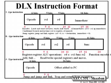
DLX Instruction Format
I - type instruction
0 5 6
10 11 15 16
31
Encodes Loads and stores of bytes, words, half
words. All immediates (rd rs1 op
immediate) Conditional branch instructions (rs1
is register, rd unused) Jump register, jump and
link register (rd 0, rs destination,
immediate 0)
R - type instruction
0 5 6
10 11 15 16
20
31
Register-register ALU operations rd rs1 func
rs2 Function encodes the data path operation
Add, Sub .. Read/write special registers
and moves.
J - Type instruction
0 5 6
31
Jump and jump and link. Trap and return from
exception
2
A Basic Multi-Cycle Implementation of DLX
- Every integer DLX instruction can be implemented
in at most five clock cycles - Instruction fetch cycle (IF)
- IR MemPC
- NPC PC 4
- Instruction decode/register fetch cycle (ID)
- A RegsIR6..10
- B RegsIR 11..15
- Imm ((IR16)16IR 16..31)
- Note IR (instruction register), NPC (next
sequential program counter register) - A, B, Imm are temporary registers
3
A Basic Implementation of DLX (continued)
- Execution/Effective address cycle (EX)
- Memory reference
- ALUOutput A Imm
- Register-Register ALU instruction
- ALUOutput A func B
- Register-Immediate ALU instruction
- ALUOutput A op Imm
- Branch
- ALUOutput NPC Imm
- Cond (A op 0)
4
A Basic Implementation of DLX (continued)
- Memory access/branch completion cycle (MEM)
- Memory reference
- LMD MemALUOutput or
- MemALUOutput B
- Branch
- if (cond) PC ALUOutput else PC
NPC - Note LMD (load memory data) register
5
A Basic Implementation of DLX (continued)
- Write-back cycle (WB)
- Register-Register ALU instruction
- RegsIR 16..20 ALUOutput
- Register-Immediate ALU instruction
- RegsIR 11..15 ALUOutput
- Load instruction
- RegsIR 11..15 LMD
- Note LMD (load memory data) register
6
A Multi-Cycle DLX Datapath Implementation
7
Pipelining Definitions
- Pipelining is an implementation technique where
multiple operations on a number of instructions
are overlapped in execution. - An instruction execution pipeline involves a
number of steps, where each step completes a part
of an instruction. - Each step is called a pipe stage or a pipe
segment. - The stages or steps are connected one to the next
to form a pipe -- instructions enter at one end
and progress through the stage and exit at the
other end. - Throughput of an instruction pipeline is
determined by how often an instruction exists the
pipeline. - The time to move an instruction one step down the
line is is equal to the machine cycle and is
determined by the stage with the longest
processing delay.
8
Pipelining Design Goals
- The length of a machine clock cycle is determined
by the time required for the slowest pipe stage. - An important pipeline design consideration is to
balance the length of each pipeline stage. - If all stages are perfectly balanced, then the
time per instruction on a pipelined machine
(assuming ideal conditions with no stalls) - Time per instruction on
unpipelined machine - Number of
pipe stages - Under these ideal conditions
- Speedup from pipelining equals the number of
pipeline stages n, - One instruction is completed every cycle, CPI
1 .
9
Simple DLX Pipelined Instruction Processing
-
Clock Number
Time in clock cycles - Instruction Number 1 2 3
4 5 6
7 8 9 - Instruction I IF ID
EX MEM WB - Instruction I1 IF
ID EX MEM WB - Instruction I2
IF ID EX
MEM WB - Instruction I3
IF ID
EX MEM WB - Instruction I 4
IF
ID EX MEM WB -
Time to fill the pipeline - DLX Pipeline Stages
- IF Instruction Fetch
- ID Instruction Decode
- EX Execution
- MEM Memory Access
- WB Write Back
10
(No Transcript)
11
A Pipelined DLX Datapath
- Obtained from multi-cycle DLX datapath by
adding buffer registers between pipeline stages - Assume register writes occur in first half of
cycle and register reads occur in second half.
12
(No Transcript)
13
Basic Performance Issues In Pipelining
- Pipelining increases the CPU instruction
throughput - The number of instructions completed per
unit time. - Under ideal condition instruction throughput
is one - instruction per machine cycle, or CPI 1
- Pipelining does not reduce the execution time of
an individual instruction The time needed to
complete all processing steps of an instruction
(also called instruction completion latency). - It usually slightly increases the execution time
of each instruction over unpipelined
implementations due to the increased control
overhead of the pipeline and pipeline stage
registers delays.
14
Pipelining Performance Example
- Example For an unpipelined machine
- Clock cycle 10ns, 4 cycles for ALU operations
and branches and 5 cycles for memory operations
with instruction frequencies of 40, 20 and
40, respectively. - If pipelining adds 1ns to the machine clock
cycle then the speedup in instruction execution
from pipelining is - Non-pipelined Average instruction execution time
Clock cycle x Average CPI - 10 ns x ((40 20) x 4 40x 5) 10 ns
x 4.4 44 ns - In the pipelined five implementation five
stages are used with an average instruction
execution time of 10 ns 1 ns 11 ns - Speedup from pipelining Instruction
time unpipelined -
Instruction time pipelined -
44 ns / 11 ns 4 times
15
Pipeline Hazards
- Hazards are situations in pipelining which
prevent the next instruction in the instruction
stream from executing during the designated clock
cycle. - Hazards reduce the ideal speedup gained from
pipelining and are classified into three classes - Structural hazards Arise from hardware
resource conflicts when the available hardware
cannot support all possible combinations of
instructions. - Data hazards Arise when an instruction depends
on the results of a previous instruction in a way
that is exposed by the overlapping of
instructions in the pipeline - Control hazards Arise from the pipelining of
conditional branches and other instructions that
change the PC
16
Performance of Pipelines with Stalls
- Hazards in pipelines may make it necessary to
stall the pipeline by one or more cycles and thus
degrading performance from the ideal CPI of 1. - CPI pipelined Ideal CPI Pipeline stall
clock cycles per instruction - If pipelining overhead is ignored and we assume
that the stages are perfectly balanced then - Speedup CPI unpipelined / (1 Pipeline
stall cycles per instruction) - When all instructions take the same number of
cycles and is equal to the number of pipeline
stages then - Speedup Pipeline depth / (1 Pipeline
stall cycles per instruction)
17
Performance of Pipelines with Stalls
- If we think of pipelining as improving the
effective clock cycle time, then given the the
CPI for the unpipelined machine and the CPI of
the ideal pipelined machine 1, then effective
speedup of a pipeline with stalls over the
unpipelind case is given by - Speedup 1
X Clock cycles unpiplined - 1 Pipeline stall cycles
Clock cycle pipelined - When pipe stages are balanced with no overhead,
the clock cycle for the pipelined machine is
smaller by a factor equal to the pipelined depth - Clock cycle pipelined clock cycle
unpipelined / pipeline depth - Pipeline depth Clock cycle unpipelined /
clock cycle pipelined - Speedup 1
X pipeline depth - 1 pipeline stall cycles per
instruction
18
Structural Hazards
- In pipelined machines overlapped instruction
execution requires pipelining of functional units
and duplication of resources to allow all
possible combinations of instructions in the
pipeline. - If a resource conflict arises due to a hardware
resource being required by more than one
instruction in a single cycle, and one or more
such instructions cannot be accommodated, then a
structural hazard has occurred, for example - when a machine has only one register file write
port - or when a pipelined machine has a shared
single-memory pipeline for data and instructions. - stall the pipeline for one cycle for register
writes or memory data access
19
(No Transcript)
20
Resolving A Structural Hazard with Stalling
21
A Structural Hazard Example
- Given that data references are 40 for a
specific instruction mix or program, and that
the ideal pipelined CPI ignoring hazards is equal
to 1. - A machine with a data memory access structural
hazards requires a single stall cycle for data
references and has a clock rate 1.05 times
higher than the ideal machine. Ignoring other
performance losses for this machine - Average instruction time CPI X Clock
cycle time - Average instruction time (1 0.4 x 1)
x Clock cycle ideal -
1.05 -
1.3 X Clock cycle time ideal
22
Data Hazards
- Data hazards occur when the pipeline changes the
order of read/write accesses to instruction
operands in such a way that the resulting access
order differs from the original sequential
instruction operand access order of the
unpipelined machine resulting in incorrect
execution. - Data hazards usually require one or more
instructions to be stalled to ensure correct
execution. - Example
- ADD R1, R2, R3
- SUB R4, R1, R5
- AND R6, R1, R7
- OR R8,R1,R9
- XOR R10, R1, R11
- All the instructions after ADD use the result of
the ADD instruction - SUB, AND instructions need to be stalled for
correct execution.
23
DLX Data Hazard Example
Figure 3.9 The use of the result of the ADD
instruction in the next three instructions causes
a hazard, since the register is not written until
after those instructions read it.
24
Minimizing Data hazard Stalls by Forwarding
- Forwarding is a hardware-based technique (also
called register bypassing or short-circuiting)
used to eliminate or minimize data hazard
stalls. - Using forwarding hardware, the result of an
instruction is copied directly from where it is
produced (ALU, memory read port etc.), to where
subsequent instructions need it (ALU input
register, memory write port etc.) - For example, in the DLX pipeline with forwarding
- The ALU result from the EX/MEM register may be
forwarded or fed back to the ALU input latches
as needed instead of the register operand value
read in the ID stage. - Similarly, the Data Memory Unit result from the
MEM/WB register may be fed back to the ALU input
latches as needed . - If the forwarding hardware detects that a
previous ALU operation is to write the register
corresponding to a source for the current ALU
operation, control logic selects the forwarded
result as the ALU input rather than the value
read from the register file.
25
Pipelined DLX with Forwarding
26
Load/Store Forwarding Example
27
Data Hazard Classification
- Given two instructions I, J, with I
occurring before J in an instruction stream - RAW (read after write) A true data
dependence - J tried to read a source before I writes
to it, so J incorrectly gets the old value. - WAW (write after write) A name dependence
- J tries to write an operand before it is
written by I - The writes end up being performed in the
wrong order. - WAR (write after read) A name dependence
- J tries to write to a destination before it
is read by I, - so I incorrectly gets the new value.
- RAR (read after read) Not a hazard.
28
Data Hazard Classification
29
Data Hazards Present in Current DLX Pipeline
- Read after Write (RAW) Hazards Possible?
- Results from true data dependencies between
instructions. - Yes possible, when an instruction requires an
operand generated by a preceding instruction
with distance less than four. - Resolved by
- Forwarding or Stalling.
- Write after Read (WAR)
- Results when an instruction overwrites the result
of an instruction before all preceding
instructions have read it. - Write after Write (WAW)
- Results when an instruction writes into a
register or memory location before a preceding
instruction have written its result. - Possible? Both WAR and WAW are impossible in the
current pipeline. Why? - Pipeline processes instructions in the same
sequential order as in the program. - All instruction operand reads are completed
before a following instruction overwrites the
operand. - Thus WAR is impossible in current DLX pipeline.
- All instruction result writes are done in the
same program order. - Thus WAW is impossible in current DLX pipeline.
30
Data Hazards Requiring Stall Cycles
- In some code sequence cases, potential data
hazards cannot be handled by bypassing. For
example - LW R1, 0 (R2)
- SUB R4, R1, R5
- AND R6, R1, R7
- OR R8, R1, R9
- The LW (load word) instruction has the data in
clock cycle 4 (MEM cycle). - The SUB instruction needs the data of R1 in the
beginning of that cycle. - Hazard prevented by hardware pipeline interlock
causing a stall cycle.
31
(No Transcript)
32
Hardware Pipeline Interlocks
- A hardware pipeline interlock detects a data
hazard and stalls the pipeline until the hazard
is cleared. - The CPI for the stalled instruction increases by
the length of the stall. - For the Previous example, (no stall cycle)
LW R1, 0(R1) IF ID EX MEM
WB SUB R4,R1,R5 IF
ID EX MEM WB AND R6,R1,R7
IF ID
EX MEM WB OR R8, R1, R9
IF ID
EX MEM WB
With Stall Cycle LW R1, 0(R1) IF
ID EX MEM WB SUB R4,R1,R5
IF ID STALL EX
MEM WB AND R6,R1,R7
IF STALL ID EX
MEM WB OR R8, R1, R9
STALL IF ID
EX MEM WB
33
(No Transcript)
34
(No Transcript)
35
(No Transcript)
36
(No Transcript)
37
Compiler Instruction Scheduling for Data Hazard
Stall Reduction
- Many types of stalls resulting from data hazards
are very frequent. For example - A B C
- produces a stall when loading the second data
value (B). - Rather than allow the pipeline to stall, the
compiler could sometimes schedule the pipeline to
avoid stalls. - Compiler pipeline or instruction scheduling
involves rearranging the code sequence
(instruction reordering) to eliminate the hazard.
38
Compiler Instruction Scheduling Example
- For the code sequence
- a b c
- d e - f
- Assuming loads have a latency of one clock cycle,
the following code or pipeline compiler schedule
eliminates stalls
Scheduled code with no stalls LW Rb,b LW
Rc,c LW Re,e ADD Ra,Rb,Rc LW Rf,f SW
a,Ra SUB Rd,Re,Rf SW d,Rd
Original code with stalls LW Rb,b LW
Rc,c ADD Ra,Rb,Rc SW a,Ra LW Re,e LW
Rf,f SUB Rd,Re,Rf SW d,Rd
39
Control Hazards
- When a conditional branch is executed it may
change the PC and, without any special measures,
leads to stalling the pipeline for a number of
cycles until the branch condition is known. - In current DLX pipeline, the conditional branch
is resolved in the MEM stage resulting in three
stall cycles as shown below
Branch instruction IF ID EX MEM
WB Branch successor IF stall
stall IF ID EX MEM WB Branch
successor 1
IF ID EX MEM WB
Branch successor 2
IF ID
EX MEM Branch successor 3
IF ID EX Branch
successor 4
IF ID Branch successor 5
IF
Three clock cycles are wasted for every branch
for current DLX pipeline
40
Reducing Branch Stall Cycles
- Pipeline hardware measures to reduce branch stall
cycles - 1- Find out whether a branch is taken earlier
in the pipeline. - 2- Compute the taken PC earlier in the
pipeline. - In DLX
- In DLX branch instructions BEQZ, BNEZ, test a
register for equality to zero. - This can be completed in the ID cycle by moving
the zero test into that cycle. - Both PCs (taken and not taken) must be computed
early. - Requires an additional adder because the current
ALU is not useable until EX cycle. - This results in just a single cycle stall on
branches.
41
Modified DLX Pipeline Conditional Branches
Completed in ID Stage
42
Compile-Time Reduction of Branch Penalties
- One scheme discussed earlier is to flush or
freeze the pipeline by whenever a conditional
branch is decoded by holding or deleting any
instructions in the pipeline until the branch
destination is known (zero pipeline registers,
control lines)). - Another method is to predict that the branch is
not taken where the state of the machine is not
changed until the branch outcome is definitely
known. Execution here continues with the next
instruction stall occurs here when the branch is
taken. - Another method is to predict that the branch is
taken and begin fetching and executing at the
target stall occurs here if the branch is not
taken
43
Predict Branch Not-Taken Scheme
44
Static Compiler Branch Prediction
- Two basic methods exist to statically predict
branches - at compile time
- By examination of program behavior and the use of
information collected from earlier runs of the
program. - For example, a program profile may show that most
forward branches and backward branches (often
forming loops) are taken. The simplest scheme in
this case is to just predict the branch as taken. - To predict branches on the basis of branch
direction, choosing backward branches as taken
and forward branches as not taken.
45
(No Transcript)
46
Profile-Based Compiler Branch
Misprediction Rates
47
(No Transcript)
48
Reduction of Branch PenaltiesDelayed Branch
- When delayed branch is used, the branch is
delayed by n cycles, following this execution
pattern - conditional branch
instruction - sequential
successor1 - sequential
successor2 - ..
- sequential
successorn -
branch target if taken - The sequential successor instruction are said to
be in the branch delay slots. These
instructions are executed whether or not the
branch is taken. - In Practice, all machines that utilize delayed
branching have - a single instruction delay slot.
- The job of the compiler is to make the successor
instructions - valid and useful instructions.
49
Delayed Branch Example
50
Delayed Branch-delay Slot Scheduling Strategies
- The branch-delay slot instruction can be chosen
from - three cases
- An independent instruction from before the
branch - Always improves performance when used. The
branch - must not depend on the rescheduled
instruction. - An instruction from the target of the branch
- Improves performance if the branch is taken
and may require instruction duplication. This
instruction must be safe to execute if the branch
is not taken. - An instruction from the fall through instruction
stream - Improves performance when the branch is not
taken. The instruction must be safe to execute
when the branch is taken. - The performance and usability of cases B, C is
improved by using - a canceling or nullifying branch.
51
(A)
(B)
(C)
52
Branch-delay Slot Canceling Branches
- In a canceling branch, a static compiler branch
direction prediction is included with the
branch-delay slot instruction. - When the branch goes as predicted, the
instruction in the branch delay slot is executed
normally. - When the branch does not go as predicted the
instruction is turned into a no-op. - Canceling branches eliminate the conditions on
instruction selection in delay instruction
strategies B, C - The effectiveness of this method depends on
whether we predict the branch correctly.
53
(No Transcript)
54
DLX Performance Using Canceling Delay Branches
55
Performance of Branch Schemes
- The effective pipeline speedup with branch
penalties (assuming an ideal pipeline CPI of
1) - Pipeline speedup
Pipeline depth - 1
Pipeline stall cycles from branches - Pipeline stall cycles from branches Branch
frequency X branch penalty - Pipeline speedup Pipeline
Depth - 1 Branch
frequency X Branch penalty
56
Pipeline Performance Example
- Assume the following DLX instruction mix
- What is the resulting CPI for the pipelined DLX
with forwarding and branch address calculation in
ID stage when using a branch not-taken scheme? - CPI Ideal CPI Pipeline stall clock cycles
per instruction - 1
stalls by loads stalls by branches - 1
.3 x .25 x 1 .2 x .45 x 1 - 1
.075 .09 - 1.165
Type Frequency Arith/Logic 40 Load 30
of which 25 are followed immediately by
an instruction
using the loaded value Store 10 branch 20
of which 45 are taken
57
Branch Penalty Example
- For a pipeline similar to the MIPS R4000, it
takes three pipeline stages before the branch
target address is known and an additional cycle
before the branch condition is evaluated. - Assuming no stalls on the registers in the
conditional comparison. The branch penalty for
the three simplest branch prediction schemes
Branch Scheme Penalty unconditional
Penalty untaken Penalty taken Flush pipeline
2.0
3 3 Predict taken
2.0 3
2 Predict untaken
2.0 0
3
58
Pipelining and Handling of Exceptions
- Exceptions are events that usually occur in
normal program execution where the normal
execution order of the instructions is changed
(often called interrupts, faults). - Types of exceptions include
- I/O device request
- Invoking an operating system service
- Tracing instruction execution
- Breakpoint (programmer-requested interrupt).
- Integer overflow or underflow
- FP anomaly
- Page fault (not in main memory)
- Misaligned memory access
- Memory protection violation
- Undefined instruction
- Hardware malfunctions
59
The names of common exceptions vary across four
different architectures.
60
Characteristics of Exceptions
- Synchronous vs. asynchronous
- Synchronous occurs at the same place
with the same data and memory allocation - Asynchronous Caused by devices external
to the processor and memory. - User requested vs. coerced
- User requested The user task requests
the event. - Coerced Caused by some hardware event.
- User maskable vs. user nonmaskable
- User maskable Can be disabled by the user
task using a mask. - Within vs. between instructions
- Whether it prevents instruction completion
by happening in the middle of execution. - Resuming vs. terminating
- Terminating The program execution always
stops after the event. - Resuming the program continues after the
event. The state of the pipeline must be saved
to handle this type of exception. The pipeline
is restartable in this case.
61
Handling of Resuming Exceptions
- A resuming exception (e.g. a virtual memory page
fault) usually requires the intervention of the
operating system. - The pipeline must be safely shut down and its
state saved for the execution to resume after the
exception is handled as follows - Force a trap instruction into the pipeline on the
next IF. - Turn of all writes for the faulting instruction
and all instructions in the pipeline. Place
zeroes into pipeline latches starting with the
instruction that caused the fault to prevent
state changes. - The execution handling routine of the operating
system saves the PC of the faulting instruction
and other state data to be used to return from
the exception.
62
Exception Handling Issues
- When using delayed branches ,as many PCs as the
the length of the branch delay plus one need to
be saved and restored to restore the state of the
machine. - After the exception has been handled special
instructions are needed to return the machine to
the state before the exception occurred (RFE,
Return to User code in DLX). - Precise exceptions imply that a pipeline is
stopped so the instructions just before the
faulting instruction are completed and and those
after it can be restarted from scratch. - Machines with arithmetic trap handlers and demand
paging must support precise exceptions.
63
Exceptions in DLX
- The following represent problem exceptions for
the DLX pipeline stages - IF Page fault on instruction
fetch misaligned memory access - memory-protection violation.
- ID Undefined or illegal opcode
- EX Arithmetic exception
- MEM Page fault on data fetch
misaligned memory access - memory-protection violation
- WB None
- Example LW IF ID EX
MEM WB - ADD
IF ID EX MEM WB
- can cause a data page fault and an
arithmetic exception at the same time ( LW in MEM
and ADD in EX) - Handled by dealing with data page fault and
then restarting execution, then the second
exception will occur but not the first.
64
Precise Exception Handling in DLX
- The instruction pipeline is required to handle
exceptions of instruction i before those of
instruction i1 - The hardware posts all exceptions caused by an
instruction in a status vector associated with
the instruction which is carried along with the
instruction as it goes through the pipeline. - Once an exception indication is set in the
vector, any control signals that cause a data
value write is turned off . - When an instruction enters WB the vector is
checked, if any exceptions are posted, they are
handled in the order they would be handled in an
unpipelined machine. - Any action taken in earlier pipeline stages is
invalid but cannot change the state of the
machine since writes where disabled.
Recommended
CrystalGraphics Presentations


