
LECTURE 2: Approaches to System Development - PowerPoint PPT Presentation
1 / 85
Title:
LECTURE 2: Approaches to System Development
Description:
OO languages: Java, C , C#, .NET, VB. 63. Object-Oriented Approach to Systems. 64 ... Current Trends in Development. More adaptive approaches. The Unified ... – PowerPoint PPT presentation
Number of Views:356
Avg rating:3.0/5.0
Title: LECTURE 2: Approaches to System Development
1
ITEC 3010 Systems Analysis and Design, I
LECTURE 2Approaches to System Development
Prof. Peter Khaiter
2
Lecture Outline
- Systems Development Life Cycle
- Phases and Activities in the SDLC
- Variations of the SDLC models
- Selecting the appropriate model
- Methodologies of the SDLC
- Traditional Approach to SDLC
- Information Engineering Approach to SDLC
- Object-Oriented Approach to SDLC
- Rapid Application Development
- Current trends in the SDLC
- CASE Tools
3
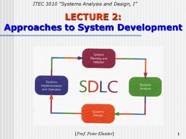
Systems Development Life Cycle
- Systems development life cycle (SDLC)?
- Provides overall framework for managing systems
development process - Two main approaches to SDLC
- Predictive approach assumes project can be
planned out in advance - Adaptive approach more flexible, assumes
project cannot be planned out in advance - All projects use some variation of SDLC
4
Predictive vs. Adaptive Approach to the SDLC
5
Phases in SDLC
- Project planning initiate, ensure feasibility,
plan schedule, obtain approval for project - Analysis understand business needs and
processing requirements - Design define solution system based on
requirements and analysis decisions - Implementation construct, test, train users,
and install new system - Support keep system running and improve
6
Systems Development Life Cycle
7
Systems Life Cycle
8
Activities of Each SDLC Phase
- Predictive or adaptive approach use SDLC
- Activities of each phase are similar
- Phases are not always sequential
- Phases can overlap
- Activities across phases can be done within an
iteration
9
Activities of Project Planning
- Define business problem and scope
- Produce detailed project schedule
- Confirm project feasibility
- Economic, organizational, technical, resource,
and schedule - Staff the project (resource management)?
- Launch project ? official announcement
10
Analysis Activities
- Gather information to learn problem domain
- Define system requirements
- Build prototypes for discovery of requirements
- Prioritize requirements
- Generate and evaluate alternatives
- Review recommendations with management
11
Design Activities
- Design and integrate the network
- Design the application architecture
- Design the user interfaces
- Design the system interfaces
- Design and integrate the database
- Prototype for design details
- Design and integrate system controls
12
Implementation Activities
- Construct software components
- Verify and test
- Convert data
- Train users and document the system
- Install the system
13
Support Activities (SLC, not SDLC)
- Maintain system
- Small patches, repairs, and updates
- Enhance system
- Small upgrades or enhancements to expand system
capabilities - Larger enhancements may require separate
development project - Support users
- Help desk and/or support team
14
FIGURE 2-2 The SDLC Phases.
15
Waterfall Approach to the SDLC
16
Waterfall Approach
- Each life cycle phase is completed in sequence
and then the results of the phase flow on to the
next phase - There is no going back once the phase is
completed (like a waterfall) or it is extremely
difficult to do - The key deliverables for each phase are typically
produced on paper (hundreds of pages in length) - The decisions made at each phase are frozen, i.e.
they cannot be changed
17
Waterfall Approach pros and cons
The two key advantages of the waterfall model
Identifying system requirements long before
programming begins It minimizes changes to the
requirements as the project proceeds The key
disadvantages The design must be completely
specified on paper before programming begins A
long time elapses between the completion of the
system proposal in the analysis phase and the
delivery of the system (usually many months or
years). A paper document is often a poor
communication mechanism, so important
requirements can be overlooked in the hundreds of
pages of documentation Users rarely are
prepared for their introduction to the new
system, which occurs long after the initial idea
for the system was introduced. If the project
team misses important requirements, expensive
post-implementation programming may be needed.
A system may require significant rework because
of changes in business environment since the time
the analysis phase occurred. It means going back
to the initial phases and following the changes
through each of the subsequent phases in turn.
18
The Parallel Model
- The Parallel Model attempts to address the
problem of long delays between the analysis phase
and the delivery of the system. - Instead of doing the design and implementation in
sequence, it performs a general design for the
whole system and then divides the project into
series of distinct subprojects that can be
designed and implemented in parallel - Once all subprojects are complete, the final
integration of the separate pieces is delivered
19
The Parallel Model
20
Parallel Model pros and cons
- Primary advantages
- Can reduce the schedule time required to deliver
a system - There is less chance of changes in the business
environment causing rework - Key disadvantages
- Still suffers from problems caused by paper
documentation - A new problem sometimes the subprojects are not
completely independent design made in one
subproject may affect another and the end of the
project may require significant integrative
efforts
21
Overlap of activities
22
Newer Adaptive Approaches to the SDLC
- Based on spiral model
- Project cycles through development activities
over and over until project is complete - Prototype created by end of each cycle
- Focuses on mitigating risk
- Iteration Work activities are repeated
- Each iteration refines previous result
- Approach assumes no one gets it right the first
time - There are a series of mini projects for each
iteration
23
Spiral Model
- Breaks each project into smaller pieces, each
with a different type of risk (Sources of risk
undefined requirements, complex technology,
uncertain competitive environment) - The project begins in the center of the spiral
where project is still small, easy to manage and
low in risk - Then the project slowly expands
- The project starts out small, initially handling
a few of the risks - Then the project expands in next iteration to
address more of the risks - Eventually the system is completed (all risks
addressed) - Advantage
- The iterative nature and focus on risk reduction
24
The Spiral Life Cycle Model
25
The Model with Iterations
- Iteration the process of looping through the
same development activities multiple times,
sometimes at increasing levels of details or
accuracy - Assumes no one gets the right results the first
time - Do some analysis, then some design, then some
implementation, then do some further analysis,
etc until you get it right - Idea not always realistic to complete analysis
before starting design - Waterfall no longer applies - Phases become
blurred - Decisions are not frozen at the end of each phase
- Applicability
- Good for projects where requirement
specifications are hard to arrive at
26
Iteration of System Development Activities
27
Phased Development Model
- Breaks the overall system into a series of
versions that are developed sequentially - The analysis phase identifies the overall system
concept. The project team, users and system
sponsors categorize the requirements into a
series of versions - The most important and fundamental requirements
are bundled into the first version of the system.
The analysis phase then leads into design and
implementation, but only with the set of
requirements identified for version 1 - Once version 1 is implemented, work begins on
version 2. Additional analysis is performed on
the basis of the previously identified
requirements and combined with new ideas and
issues that arose from users experience with
version 1. - Version 2 then is designed and implemented, and
work immediately begins on the next version. This
process continues until the system is complete
28
Phased Model
29
Phased Model pros and cons
- Advantages Quickly getting a useful system into
the hands of users. Although it does not perform
all the functions the users need, it helps them
sooner to identify important additional
requirements - Disadvantages The users begin to work with
systems that are incomplete. It is critical to
identify the most important and useful features
and include them in the first version.
30
Just For Fun
http//www.funnyhumor.com/pictures/206.php
31
Prototyping model
- Performs analysis, design and implementation
phases concurrently, and all three phases are
performed repeatedly in a cycle until the system
is completed. - The basics of analysis and design are performed,
and work immediately begins on a system prototype
(i.e., a quick-and-dirty program that provides
a minimal amount of features - The first prototype is shown to the users and the
project sponsor, who provide comments, which are
used to re-analyze, re-design, and re-implement a
second prototype that provides a few more
features - This process continues in a cycle until the
analysts, users and sponsor agree that the
prototype provides enough functionality to be
installed and used. Refinement occurs until it is
accepted as the new system.
32
Prototyping SDLC
33
Prototyping model pros and cons
- The key advantages
- Very quickly provides a system for users to
interact with. It reassures the users that the
project team is working on the system. The users
can interact with the prototype to better
understanding what it can and cannot do rather
than attempting to understand a system
specification on paper. - The major disadvantages
- Fast-paced system releases challenge attempts
to conduct careful, methodical analysis. Often
the prototype undergoes such significant changes
that many initial design decisions become poor
ones. This can cause problems in the development
of complex systems because fundamental issues and
problems are not recognized until well into the
development process.
34
Throwaway Prototyping
- Similar to the prototyping model in that it
includes the development of prototypes, however,
they are done at a different point in the SDLC - Has a relatively thorough analysis phase that is
used to gather information and to develop ideas
for the system concept. Many of the features
suggested by the users may not be well understood
and many technical issues may not be solved. - Each of these issues are examined by analyzing,
designing and building a design prototype (it is
not a working system it only represents a part
of the system that needs additional refinement
and it contains only enough details to enable
users to understand the issues under
consideration) - Typically, several prototypes are used during
analysis and design phase. Each of them is used
to minimize the risk of missing of important
issues before the real system is built. - Once the issues are resolved, the project moves
into design and implementation. At this point,
the design prototypes are thrown away, what is a
principal difference between this model and
prototyping, in which the prototypes evolve into
the final system
35
Throwaway Prototyping Model
36
Throwaway Prototyping pros and cons
- Balances the benefits of well-through-out
analysis and design phases with the advantages of
using prototypes to refine key issues before a
system is built. - It may take longer to deliver the final system
as compared with prototyping (as far as the
prototypes do not become the final system), but
this model usually produces more stable and
reliable systems.
37
Criteria for Selecting the Appropriate Model of
SDLC
38
Criteria for Selecting
Clarify of user requirements Sometimes the user
requirements are unclear or subject to change.
Prototyping and throwaway prototyping are more
appropriate models for such situations, because
they provide prototypes for user to interact with
at early stages of the SDLC. Familiarity with
Technology When the system will use new
technology, which is unfamiliar for the analysts
and programmers (e.g. the first Web-based project
with Java), it increases the risks. Application
of the new technology as early as possible will
improve the chance of success. Throwaway
prototyping is particularly appropriate for this
situation since it explicitly encourages the
developers to develop design prototypes for areas
with high risks. Phased model is good as well
because it creates opportunities to investigate
the technology in some depth before the design is
complete. System Complexity Complex systems
require careful and detailed analysis and design.
Throwaway prototyping is particularly well suited
to such situation, but prototyping is not. The
traditional structured methodologies can handle
complex systems, but without the ability to get
the system or prototypes into users hands early
on, some key issues may be overlooked. Even
though the phased model enables users to interact
with the system early in the process.
39
Criteria for Selecting
Short time schedules Projects with short time
schedules are well suited for RAD models as far
as they are designed to increase the speed of
development. Prototyping and phased development
are excellent choices because they best enable
the project team to adjust the functionality in
the system. If the project schedule starts to
slip, it can be readjusted by removing
functionality from the version or prototype under
development. The waterfall model is the worst
choice, because it does not allow for easy
schedule changes. Schedule visibility One of the
greatest challenges in systems development is
knowing whether a project is on schedule. This is
particularly true of the structured methods
because design and implementation occur at the
end of the project. The RAD models move many of
the critical design decisions to an earlier point
in the project to help project managers to
recognize and address risk factors and keep
expectations in check.
40
Methodologies
- Methodologies
- Comprehensive guidelines to follow for completing
every SDLC activity - Collection of models, tools, and techniques
41
Relationships Among Components of a Methodology
42
Models
- Models
- Representation of an important aspect of real
world, but not same as real thing - Abstraction used to separate out aspect
- physical (like a model of an airplane)
- abstract (e.g. in form of mathematical
notation or in graphical form) - Models in SDLC are graphical diagrams and charts
- Project planning and budgeting aids
43
Some Models Used in SDLC
44
Tools
- Tools
- Software support that helps create models or
other required project components - Range from simple drawing programs to complex
CASE tools to project management software
45
Some Tools Used in SDLC
46
Techniques
- Techniques
- Collection of guidelines that help analysts
complete a system development activity or task - Can be step-by-step instructions or just general
advice
47
Some Techniques Used in SDLC
48
Two Approaches to System Development
- Traditional approach
- Also called structured system development
- Structured analysis and design technique (SADT)?
- Includes information engineering (IE)?
- Object-oriented approach
- Also called OOA, OOD, and OOP
- Views information system as collection of
interacting objects that work together to
accomplish tasks
49
Structured Analysis
- Define what system needs to do (processing
requirements)? - Define data system needs to store and use (data
requirements)? - Define inputs and outputs
- Define how functions work together to accomplish
tasks - Data flow diagrams (DFD) and entity relationship
diagrams (ERD) show results of structured
analysis
50
Data Flow Diagram (DFD) Created Using Structured
Analysis Technique
51
Entity-Relationship Diagram (ERD) Created Using
Structured Analysis Technique
52
Structured Analysis Leads to Structured Design
and Structured Programming
53
Structured Design
- Technique developed to provide design guidelines
- What set of programs should be
- What program should accomplish
- How programs should be organized into a hierarchy
- Modules are shown with structure chart
- Main principle of program modules
- Loosely coupled module is independent of other
modules - Highly cohesive module has one clear task
54
Structure Chart Created Using Structured Design
Technique
55
Traditional Approach Structured Programming
- Structured programming
- Improves computer program quality
- Allows other programmers to easily read and
modify code - Each program module has one beginning and one
ending - Three programming constructs (sequence, decision,
repetition)?
56
Three Structured Programming Constructs
57
Top-Down Programming
- Divides complex programs into hierarchy of
modules - The module at top controls execution by calling
lower level modules - Modular programming
- Similar to top-down programming
- One program calls other programs to work together
as single system
58
Top-Down or Modular Programming
59
Weaknesses of the Structured Approach
Techniques address some but not all of the
activities of analysis and design Techniques
make system development not enough formal (not
like an engineering discipline) but rather like
an art. The transition from the data flow
diagram (in structured analysis) to the structure
chart (in structured design) did not work well in
practice. data modeling using structure chart
and ER diagram were more important than modeling
of processes (using dataflow diagrams)
However, the structured approach overall still
made processes rather than data the central focus
of the system Many felt a strategic planning
technique needed to be included in the approach
to determine which systems to be built and to
provide some initial requirements. As an
alternative information engineering.
60
Information Engineering (IE)?
- Focus on strategic planning to identify all the
organization information needs (the application
architecture plan), data modeling, and automated
tools - More focused on data itself than the structured
approach. But just as the structural approach
includes data requirements, IE includes
processes, too - The processing model of information engineering,
the process dependency diagram, is similar to a
data flow diagram, but it focuses more on which
processes are dependent on other processes and
less on data inputs and outputs - Provides more complete life cycle support through
the use of an integrated CASE tools (help to
automate systems development final program code
can be generated automatically by the CASE tools) - Became popular on large-mainframe systems in the
1980s, less used in the 1990s on smaller
desktop systems (but concepts still used by
planning and emphasis on data modeling)
61
Structured Approach and IE
- Both approaches define information system
requirements, design and construct information
systems by looking at processes, data and the
interaction of these two - Industry merged key concepts from structured
development and information engineering
approaches into traditional approach - An object-oriented technology provides a
completely different perspective
62
Object-Oriented Approach
- Completely different approach to information
systems - Views information system as collection of
interacting objects that work together to
accomplish tasks - Objects things in computer system that can
respond to messages - Conceptually, no processes, programs, data
entities, or files are defined just objects - OO languages Java, C, C, .NET, VB
63
Object-Oriented Approach to Systems
64
Object-Oriented Approach (continued)?
- Object-oriented analysis (OOA)?
- Defines types of objects users deal with
- Shows use cases are required to complete tasks
- Object-oriented design (OOD)?
- Defines object types needed to communicate with
people and devices in system - Shows how objects interact to complete tasks
- Refines each type of object for implementation
with specific language of environment - Object-oriented programming (OOP)?
- Writing statements in programming language to
define what each type of object does
65
Class Diagram Created During OO Analysis
66
SDLC Variations
- Many variations of SDLC in practice
- Based on variation of names for phases
- No matter which one, activities/tasks are similar
- Some increase emphasis on people
- User-centred design, participatory design
- Socio-technical systems
- Some increase speed of development
- Rapid application development (RAD)?
- Prototyping
67
Rapid Application Development
- Rapid application development (RAD) is one of
the variations of SDLC - Aims to speed up the development process.
- Emerged in the 1990s as an attempt to address
both weaknesses of the waterfall development
long development times and the difficulty in
understanding a system from paper-based
description. - Methods
- Tries to speed up the activities in each phase
(e.g. speeding the analysis phase by scheduling
intensive meetings of key participants to get
information gathered and decisions made rapidly) - Using iterative development (e.g., spiral life
cycle model) to speed up the process of getting
to design and implementation - Building prototypes of the system during
analysis and design phases. It improves
understanding of the system requirements - Using CASE (computer-aided system engineering)
tools to speed up the analysis, design and
implementation phases
68
Current Trends in Development
- More adaptive approaches
- The Unified Process (UP)?
- Extreme Programming (XP)?
- Scrum
- Details on each in Chapter 17
69
The Unified Process (UP)?
- Object-oriented development approach
- Offered by IBM / Rational
- Booch, Rumbaugh, Jacobson
- Unified Modeling Language (UML) used primarily
for modeling - UML can be used with any OO methodology
- UP defines four life cycle phases
- Inception, elaboration, construction, transition
- Defines workflows within each phase business
modeling, requirements modeling, analysis and
design, implementation, testing, development,
configuration and change management, and project
management - Involves roles of designer, use case specifier,
systems analyst, implementer, architect
70
Unified Process Life Cycle
71
The Unified Process (UP) (continued)?
- Reinforces six best practices
- Develop iteratively
- Define and manage system requirements
- Use component architectures
- Create visual models
- Verify quality
- Control changes
72
Extreme Programming (XP)?
- Recent, lightweight, development approach to keep
process simple and efficient - Describes system support needed and required
system functionality through informal user
stories - Has users describe acceptance tests to
demonstrate defined outcomes - Relies on continuous testing and integration,
heavy user involvement, programming done by small
teams
73
Scrum
- For highly adaptive project needs
- Respond to situation as rapidly as possible
- Scrum refers to rugby game
- Both are quick, agile, and self-organizing
- Team retains control over project
- Values individuals over processes
74
Computer-Aided System Engineering (CASE) Tools
- CASE tools are software tools designed to help
systems analyst complete development tasks - The CASE tool contains a database of information
called a repository - The repository stores information about the
system, including models, descriptions, and
references that link the various model together - Information stored in repository can be used in a
variety of ways by the development team - Every time a team member adds information about
the system, it is immediately available for
everyone else - CASE tools can check the models to make sure they
are complete and follow the correct diagramming
rules - CASE tools can check one model against another to
make sure they are consistent
75
Visual Modeling Tool Repository Contains All
System Information
76
CASE Tools Examples
- Microsoft Visio
- a drawing tool suitable for about any system
model - comes with a collection of drawing templates
(incl. symbols used in a variety of business and
engineering applications flowcharts, DFDs, ERDs,
UML diagrams) - provides only a limited repository for storing
definitions and descriptions of diagram elements,
but not a complete repository for a system
development project.
77
Visio for drawing a variety of diagrams and
charts
78
CASE Tools Examples (contd)
- Oracle Designer
- a tool set for recording definitions and
automating the rapid constructions of flexible,
graphical client-server applications - integrated with Oracle Developer (a tool for
creating GUI applications) - includes a complete repository, diagramming and
code-generating capabilities - an integrated CASE tool that supports
traditional approach to system development
(process modeler, function-hierarchy diagrammer,
data flow diagrammer, entity-relationship
diagrammer) - Design Transformer and Design Editor produce
diagrams along with the database and application
logic
79
Oracle Designer Front Panel screen
80
Oracle Designer Entity-Relationship Diagrammer
81
CASE Tools Examples (contd)
- TogetherSoft
- The most recent concept of round-trip
engineering - allows synchronizing the graphical models (such
as class diagram) with generated program code
(automation in both directions round trip). - If the program code is changed, the class
diagram is updated and contra versa, if the class
diagram is changed, the program code is updated. - Together uses UML diagrams with several
different programming languages
82
Together showing a class diagram with
synchronized Java source code
83
CASE Tools Examples (contd)
- Embarcadero Describe
- a new product that include modeling and
round-trip engineering features - provides flexible UML modeling capabilities for
analysis and design - provides round-trip engineering with several
Java development tools (JBuilder and Sum Forte)
84
Embarcadero Describe with visual modeling and
round-trip engineering
85
Readings
Todays lecture Chapter 2 Approaches to
System Development For next lecture Chapter 3
The Analyst as a Project Manager
Thank you !!!
Recommended
CrystalGraphics Presentations


