
Cosmicray Shield Toroid: Crew Shielding for a Manned Mars Mission - PowerPoint PPT Presentation
1 / 45
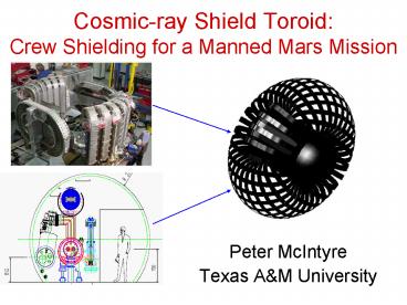
Title: Cosmicray Shield Toroid: Crew Shielding for a Manned Mars Mission
1
Cosmic-ray Shield ToroidCrew Shielding for a
Manned Mars Mission
- Peter McIntyre
- Texas AM University
2
Cosmic rays present a life threat to astronauts
on long space missions
- Protons from solar flares
- Ions from galactic cosmic rays
- Dose is equal from all nuclei
- Enough to kill a man if unshielded
- Must shield to 100 MeV/nucleon?
- 1 GeV/nucleon?
Z
3
Existing data on radiation flux beyond the
magnetosphere
Shielding requires
The devil is in the details of particle transport
through the CST envelope, including neutrons.
4
AMS Design Concept Nested Toroids
Fe
B0 Outside
Field only where it is needed minimum constraint
upon EVA safety Magnet structure independent of
crew compartment, other systems
5
The Texas AM group is interested in joining your
effort to develop a Cosmic-ray Shield Toroid
- Issues that we have considered
- Optimize coil geometry for minimum mass
- pure tension D geometry?
- Optimize cryogenic cooling for cryostability
- Supercritical He?
- Optimize conductor for cryostability
- Al-stabilized, MMC-reinforced Nb3Sn?
- Optimize particle transport to maximize shielding
- He blanket to attenuate neutrons?
6
What do we do?New Materials and Electromagnetics
in Superconducting Magnet Technology
- Nb3Sn block-coil dipoles to extend collider bend
field to 16 T - Bi-2212 coil technology for a 25 T hybrid dipole
LHC Tripler - Structured cable for internally cooled Nb3Sn and
Bi-2212 coils - Novel superconducting magnets for LHC insertions
regions - New process technology for extending perfornace
of MgB2
7
1) Hybrid Dipoleshow to triple the energy of LHC
- Peter McIntyre, Akhdiyor Sattarov
- Texas AM University
Presentation to CERN LHC Seminar 14/3/2005
p-mcintyre_at_physics.tamu.edu
8
Discovery reach for sparticles
- Ellis et al have calculated the masses of the
lightest 2 visible sparticles in minimum
supersymmetric extension of the Standard Model
(MSSM), constrained by the new results from
astrophysics and cosmology.
observable in WIMP searches (?gt 10-8 pb)
X observable at LHC
only observable at LHC Tripler
9
1a) Triple the energy of LHCHigher field
requires new superconductor, handling immense
stress loads
Nb3Sn
Nb3Sn
NbTi
Bi-2212
Bi-2212
Cost today NbTi 100/kg Nb3Sn 1,000/kg Bi-22
12 2,000/kg
10
To push to higher field use high-field
superconductor, limit coil stress
- Nb3Sn 14 Tesla dipole
New result 1/2006 latest single-layer model
dipole reached gt93 short sample on 1st quench
- Maximum Coil Stress 120 MPa
- Superconductor cross section 29 cm2
- Bore field 14.1 T
- Current 12.6 kA
11
Nb3Sn dipole technology at Texas AM stress
management, flux plate, bladder preload
12
Stress management
13
Horizontal steel flux plate redistributes flux
to suppress multipoles
0.5 T 12 T
Suppress snap-back x5, relax requirements on
filament size in Nb3Sn and Bi-2212.
14
Extend to 24 TeslaBi-2212 in inner (high field)
windings, Nb3Sn in outer (low field) windings
Dual dipole (ala LHC) Bore field 24
Tesla Max stress in superconductor
130
MPa Superconductor x-section Nb3Sn 26
cm2 Bi-2212 47 cm2 Cable current 25
kA Beam tube dia. 50 mm Beam separation 194
mm
15
1b) Remove 500 kw of synchrotron light!
- Synchrotron radiation power/length
- critical energy
- Use photon stop
- Instead of intercepting photons at 10 K along
dipole beam tube, intercept between dipoles
on room-temperature finger. - Soft X-rays actually easier to trap that hard UV
LHC E 7 TeV P 0.22 W/m Ec 44
eV (hard UV) scatters, desorbs LHC Tripler E
20 TeV P 14 W/m Ec 1.2 keV (soft
X-ray) absorbs!
16
Photon Stop
- Photoemission yields vanish for E gt 100 eV
Vertical penetration through flux return (coils
have clearance)
Effect on ltb3gt 10-5 cm-2
17
Photon stop swingsclears aperture at injection
energy, collects light at collision energy
Injection Collision
150 W/stop collected _at_ 1 W/cm2 heat transfer to
Liquid Xe (160 K) Same refrigeration power for
Tripler as for LHC!
18
Magnets are getting more efficient!
Bi-2212
NbTi
SuperSPS
Nb3Sn
19
2) The intersection region of LHC is analogous to
the objective of a microscope
- It brings the beams into collision and focuses
them to minimum spot size ? maximum luminosity - Need to minimize focal length f, minimize
chromatic aberrations df/dE, harmonic distortion
df/dr - Minimize chromaticity and distortion by bringing
the objective as close to the object as possible.
Inquire with experiments how close to go 12 m
from crossing, 30 cm radius clear. - Maximize gradient to minimize focal length
- Develop designs for quadrupoles, dipoles that can
tolerate high radiation, high heat
20
Optimized IR for LHC
21
Q1 is in harms way, but moving closer actually
reduces losses
Q1
D1
Multiplicity f(?) e-bt Eparticle pt /? So
energy flow concentrates strongly down the beam
direction.
22
Design Q1 using structured cable
6-on-1 cabling of Nb3Sn strand around thin-wall
inconel X750 spring tube Draw within a thicker
inconel 718 jacket Interior is not impregnated
only region between cables in winding Volumetric
cooling to handle volumetric heating from
particle losses
23
Ironless Quadrupole for Q1
350 T/m 4-7 K supercritical cooling
24
D1 levitated-pole dipole
8.7 T 4.5 K
particles from collisions
Cold iron pole piece, warm iron flux
return. Cancel Lorentz forces on coils, pole
steel.
25
This approach to IR elements opens new
opportunities to optimize IR optics
Comparison to baseline IR Reduce ? Reduce of
subsidiary bunch crossings Reduce sensitivity to
error fields and placements Open space for
another doublet to fully separate corrections in
x, y.
26
3) 30 T NMR using strain-tolerant Bi-2212
technology
27
Stress management within Bi-2212 cable
28
Structured cable for Bi-2212 manage stress
within cable, refrigerate with He flow in cable
Bi-2212 0.8 mm ? strands 300 A/strand
6-on-1 cabling of round strand around thin-wall
Inconel X750 spring tube Draw within a thicker
Inconel 718 jacket Interior is not impregnated
only region between cables in winding Volumetric
cooling to handle volumetric heating from
resistive losses.
29
Fabricating the cable
Winding 6-on-1 cable onto spring tube
Drawing outer shell onto cable
30
We enjoy taking on difficult challengesCST is
clearly a difficult challenge
- Optimize the trade-offs between cryostability and
minimum mass - Develop Nb3Sn conductor with Al stabilizer and
internal stress management - Develop coil system that is space-capable
31
Coil Geometry
- A key challenge to minimize mass is to manage
Lorentz stress
ITER
Straight coil segments Pure tension D
windings - forces must be supported by struts
minimum total structure mass
32
Cryogenics
- Toroid windings are large, long flow paths.
- Windings must be cryostable (or close to it!)
- Operating parameters Iop current, Top
temperature, Bop max magnetic field at
conductor - Choose parameters so that there is a substantial
margin ?T - If a local region of conductor quenches,
the quench will heal and not
propagate
33
Example for caution the Nb3Sn outsert coil of
the 45 T NHMFL hybrid nearly failed in quench!
14 T Nb3Sn coil, cable-in-conduit Superfluid
cooled, not cryostable Quench initiated in inner
region of coil Local phase transition in
superfluid He boiled dry in quenched
zone Conductor reached temp limit for damage Lost
2 Tesla of field capability The lesson in a
long-geometry coil, it is vital to force
flow That is difficult to do without potential
failure modes in superfluid
34
Simulate current transfer, heat transfer in
supercritical flow
Quench heals
Quench heals
Static modeling ignore He flow, examine the fate
of a hot zone as current bypasses through Al,
heat transfers to Al and He. The quench either
heals or propagates.
35
Nb3Sn conveys advantages for cryostability, mass
reductionbut how to bond it with Al stabilizer?
3 mm
800 A
1 m dia.
- Wind Cu-stabilized Nb3Sn round strand onto
1m-dia. spool. - .Retract rollers, heat treat to form
superconducting phase. - Extend rollers, spiral strand off spool, tin with
solder. - Apply Al stabilizer from inside, Al MMC
structural tape from outside. - Flow solder in 50 cm hot zone.
Conductor never decreases radius during coil
winding never placed in tension after reaction.
36
3M has developed a Nextel-Al metal-matrix
composite (MMC)
- Yield strength along fiber run is 1.6 GPa!
- 3M fabricates high-strength parts this way,
- They are about to begin developing a process line
to make long-run lengths of continuous tape. - A thin tape of Al MMC could be bonded to the
outside surface of the conductor integrate
stress management directly into every turn of the
coils.
37
Assemble and solder reacted strand, stabilizer,
and support tape and solder no strain to strand
Heat compress to solder
Quench cool
Pre-tinned Al MMC structural tape
Completed conductor
Tin strand, Al channel
Reacted Nb3Sn strand (1 m spool)
Pure Al channel (0.8 m spool)
38
CST central barrel using pure tension
He supply-return
32 windings attach on inner boundary Roman arch
under symmetric compression
39
Inner straight leg of one winding
Helium supply/return are manifolded through side
slots cut through extruded channels
40
How much is needed for what level of
radiation shielding?
Consider neutrons reaching the crew
He
Al
Suppose we stored the inventory of liquid He in a
cylindrical layer along then inner boundary of
the toroid. He does 5 times more scattering of
fast neutrons than aluminum, relative to strong
cross-section that produces neutrons. It should
attenuate neutron flux reaching the crew by that
factor.
41
What does all this mean for the mass of CST?
- We did one design exercise in which we assumed a
field integral of 14 Tm, and imposed
cryostability threshold corresponding to a local
zone temperature of 15 K (very conservative) - Mass requirements
- 6 m3 of structure, 12 m3 of stabilizer ? 52 T
- Do we need 15 K stability? Is 10 K enough? M/2
- Do we need 14 Tm bending? Is 7 Tm enough? M/2
- With those changes, total mass is 13 T.
- We need to do the many immense tasks for a
serious conceptual design before credible mass
estimates are possible.
42
The Texas AM group would like to join AMS to
help with the development of this extension of
the AMS magnet technology for CST
- Stress analysis of coil geometries, optimization
for minimum mass - Conductor design for cryostable operation
- Develop fabrication of Al-stabilized,
MMC-reinforced Nb3Sn conductor - Heat transfer design for refrigeration
- Particle tracking, radiation dose estimation
43
The people of our group
- Leadership Al McInturff
- Peter McIntyre
- Calculations simulations Dior Sattarov
- Technicians Ray Blackburn Tim Elliott
- Bill Henchel
- Andrew Jaisle
- Tool Die Maker Nick Diaczenko
- 2 graduate students, 2 undergraduates
44
We have experience working with industry to
develop technology
- In 1984 we developed the worlds longest
superconducting magnets - 45 m long 3 T superferric dual dipoles for the
SSC - Development was done in partnership with General
Dynamics. - After 7 m prototypes in our lab, GD built 4
full-length dipoles, shipped them San Diego-Texas - All magnets met specs, all ahead of schedule
- In 1993 we developed the worlds first
self-shielded high-field MR spectroscopy
solenoid. - Development done in partnership with Varian.
- 5 G line at edge of cryostat
- Project was on spec, on schedule.
45
The Aggies may not be the last to join your
experiment!
AMS!
MARS
TO JOIN
WANTS
Recommended
CrystalGraphics Presentations


