
The Standard 12 Lead ECG - PowerPoint PPT Presentation
1 / 42
Title:
The Standard 12 Lead ECG
Description:
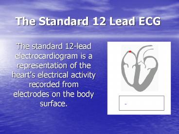
The Standard 12 Lead ECG The standard 12-lead electrocardiogram is a representation of the heart's electrical activity recorded from electrodes on the body surface. – PowerPoint PPT presentation
Number of Views:505
Avg rating:3.0/5.0
Title: The Standard 12 Lead ECG
1
The Standard 12 Lead ECG
- The standard 12-lead electrocardiogram is a
representation of the heart's electrical activity
recorded from electrodes on the body surface.
2
The Standard 12 Lead ECG
3
ECG Waves and Intervals
- This diagram illustrates ECG waves and intervals
as well as standard time and voltage measures on
the ECG paper.
4
What do they mean?
- P wave the sequential activation
(depolarization) of the right and left atria - QRS complex right and left ventricular
depolarization (normally the ventricles are
activated simultaneously) - ST-T wave ventricular repolarization
- U wave origin for this wave is not clear - but
probably represents "after depolarizations" in
the ventricles
5
What do they mean?
- PR interval time interval from onset of
atrial depolarization (P wave) to onset of
ventricular depolarization (QRS complex) QRS
duration duration of ventricular muscle
depolarization QT interval duration of
ventricular depolarization and repolarization
RR interval duration of ventricular cardiac
cycle (an indicator of ventricular rate) PP
interval duration of atrial cycle (an indicator
of atrial rate)
6
Orientation of the 12 Lead ECG
- It is important to remember that the 12-lead ECG
provides spatial information about the heart's
electrical activity in 3 approximately orthogonal
directions - Right Left
- Superior Inferior
- Anterior Posterior
7
Each of the 12 leads represents a particular
orientation in space
- Bipolar limb leads (frontal plane)
- Lead I RA (-) to LA () (Right Left, or
lateral) Lead II RA (-) to LF () (Superior
Inferior) Lead III LA (-) to LF () (Superior
Inferior)
8
Each of the 12 leads represents a particular
orientation in space
- Augmented unipolar limb leads (frontal plane)
- Lead aVR RA () to LA LF (-)
(Rightward) Lead aVL LA () to RA LF (-)
(Leftward) Lead aVF LF () to RA LA (-)
(Inferior)
9
Each of the 12 leads represents a particular
orientation in space
- Unipolar () chest leads (horizontal plane)
Leads V1, V2, V3 (Posterior Anterior) Leads
V4, V5, V6(Right Left, or lateral)
10
Behold Einthoven's Triangle!
11
Each of the 6 frontal plane leads has a negative
and positive orientation (as indicated by the ''
and '-' signs).
12
Standard Limb Leads
13
LOCATION OF CHEST ELECTRODES
14
LOCATION OF CHEST ELECTRODES
- V1 right 4th intercostal space
- V2 left 4th intercostal space
- V3 halfway between V2 and V4
- V4 left 5th intercostal space, mid-clavicular
line - V5 horizontal to V4, anterior axillary line
- V6 horizontal to V5, mid-axillary line
15
Augmented Vector Leads
- Lead aVR or "augmented vector right" has the
positive electrode (white) on the right arm. The
negative electrode is a combination of the left
arm (black) electrode and the left leg (red)
electrode, which "augments" the signal strength
of the positive electrode on the right arm. - Lead aVL or "augmented vector left" has the
positive (black) electrode on the left arm. The
negative electrode is a combination of the right
arm (white) electrode and the left leg (red)
electrode, which "augments" the signal strength
of the positive electrode on the left arm. - Lead aVF or "augmented vector foot" has the
positive (red) electrode on the left leg. The
negative electrode is a combination of the right
arm (white) electrode and the left arm (black)
electrode, which "augments" the signal of the
positive electrode on the left leg.
16
A Method for Interpretation
- Measurements
- Rhythm Analysis
- Conduction Analysis
- Waveform Description
- Ecg Interpretation
- Comparison with Previous ECG (if any)
17
Measurements (usually made in frontal plane
leads)
18
Measurements ..
- Heart rate (state atrial and ventricular, if
different) - PR interval (from beginning of P to beginning of
QRS) - QRS duration (width of most representative QRS)
- QT interval (from beginning of QRS to end of T)
19
Rhythm Analysis
- State basic rhythm (e.g., "normal sinus
rhythm", "atrial fibrillation", etc.)
Identify additional rhythm events if present
(e.g., "PVC's", "PAC's", etc) Consider all
rhythm events from atria, AV junction, and
ventricles
20
Conduction Analysis
- The following conduction abnormalities are to be
identified if present - SA block 2nd degree (type I vs. type II)
- AV block 1st, 2nd (type I vs. type II), and 3rd
degree - IV blocks bundle branch, fascicular, and
nonspecific blocks
21
Waveform Description
- Carefully analyze the 12-lead ECG for
abnormalities in each of the waveforms in the
order in which they appear P-waves, QRS
complexes, ST segments, T waves, and... Don't
forget the U waves.
22
Waveform Description
- P waves are they too wide, too tall, look funny
(i.e., are they ectopic), etc.? - QRS complexes look for pathologic Q waves ,
abnormal voltage , etc. - ST segments look for abnormal ST elevation
and/or depression. - T waves look for abnormally inverted T waves.
- U waves look for prominent or inverted U waves.
23
ECG Interpretation
- This is the conclusion of the above analyses.
Interpret the ECG as "Normal", or "Abnormal".
Occasionally the term "borderline" is used if
unsure about the significance of certain
findings. List all abnormalities. Examples of
"abnormal" statements are
24
Examples of abnormalities
- Inferior MI, probably acute Old
anteroseptal MI Left anterior fascicular
block (LAFB) Left ventricular hypertrophy
(LVH) Nonspecific ST-T wave abnormalities
Any rhythm abnormalities
25
EKG Report example..
- Left Anterior Fascicular Block (LAFB)
- HR72bpm PR0.16s QRS0.09s QT0.36s QRS axis
-70o (left axis deviation) Normal sinus
rhythm normal SA and AV conduction rS in leads
II, III, aVF Interpretation Abnormal ECG
1)Left anterior fascicular block
26
Characteristics of the Normal ECG
- It is important to remember that there is a wide
range of normal variability in the 12 lead ECG.
The following "normal" ECG characteristics,
therefore, are not absolute. It takes
considerable ECG reading experience to discover
all the normal variants.
27
Characteristics of the Normal ECG
- Heart Rate 60 - 90 bpm How to calculate the
heart rate on ECG paper PR Interval 0.12 -
0.20 sec QRS Duration 0.06 - 0.10 sec QT
Interval (QTc lt 0.40 sec) Poor Man's Guide
to upper limits of QT For HR 70 bpm, QTlt0.40
sec for every 10 bpm increase above 70 subtract
0.02 sec, and for every 10 bpm decrease below 70
add 0.02 sec. For example QT lt 0.38 _at_ 80 bpm
QT lt 0.42 _at_ 60 bpm - Frontal Plane QRS Axis 90 o to -30 o (in the
adult)
28
Characteristics of the Normal ECG
- Rhythm
- Normal sinus rhythmThe P waves in leads I and
II must be upright (positive) if the rhythm is
coming from the sinus node. - Conduction
- Normal Sino-atrial (SA), Atrio-ventricular (AV),
and Intraventricular (IV) conductionBoth the PR
interval and QRS duration should be within the
limits specified above.
29
Waveform Description
- P Wave It is important to remember that the P
wave represents the sequential activation of the
right and left atria, and it is common to see
notched or biphasic P waves of right and left
atrial activation. P duration lt 0.12 sec P
amplitude lt 2.5 mm Frontal plane P wave axis
0o to 75o May see notched P waves in frontal
plane
30
Waveform Description
- QRS Complex The QRS represents the
simultaneous activation of the right and left
ventricles, although most of the QRS waveform is
derived from the larger left ventricular
musculature. QRS duration lt 0.10 sec QRS
amplitude is quite variable from lead to lead and
from person to person. Two determinates of QRS
voltages are Size of the ventricular chambers
(i.e., the larger the chamber, the larger the
voltage) Proximity of chest electrodes to
ventricular chamber (the closer, the larger the
voltage)
31
Atrio-Ventricular (AV) Block
- Possible sites of AV block
- AV node (most common)
- His bundle (uncommon)
- Bundle branch and fascicular divisions (in
presence of already existing complete bundle
branch block)
32
1st Degree AV Block
- PR interval gt 0.20 sec all P waves conduct to
the ventricles.
33
2nd Degree AV Block
- In "classic" Type I (Wenckebach) AV block the
PR interval gets longer (by shorter increments)
until a nonconducted P wave occurs. The RR
interval of the pause is less than the two
preceding RR intervals, and the RR interval after
the pause is greater than the RR interval before
the pause. These are the classic rules of
Wenckebach (atypical forms can occur). In Type II
(Mobitz) AV block the PR intervals are constant
until a nonconducted P wave occurs.
34
2nd Degree AV Block
35
Type I (Wenckebach) AV block (note the RR
intervals in ms duration)
36
Type II (Mobitz) AV block(note there are two
consecutive constant PR intervals before the
blocked P wave)
37
- Type II AV block is almost always located in the
bundle branches, which means that the QRS
duration is wide indicating complete block of one
bundle the nonconducted P wave is blocked in the
other bundle. In Type II block several
consecutive P waves may be blocked as illustrated
below
38
Complete (3rd Degree) AV Block
- Usually see complete AV dissociation because
the atria and ventricles are each controlled by
separate pacemakers. Narrow QRS rhythm
suggests a junctional escape focus for the
ventricles with block above the pacemaker focus,
usually in the AV node. Wide QRS rhythm
suggests a ventricular escape focus (i.e.,
idioventricular rhythm). This is seen in ECG 'A'
below ECG 'B' shows the treatment for 3rd degree
AV block i.e., a ventricular pacemaker. The
location of the block may be in the AV junction
or bilaterally in the bundle branches.
39
ECG Recognition of Myocardial Infarction
- When myocardial blood supply is abruptly reduced
or cut off to a region of the heart, a sequence
of injurious events occur beginning with
subendocardial or transmural ischemia, followed
by necrosis, and eventual fibrosis (scarring) if
the blood supply isn't restored in an appropriate
period of time. Rupture of an atherosclerotic
plaque followed by acute coronary thrombosis is
the usual mechanism of acute MI. The ECG changes
reflecting this sequence usually follow a
well-known pattern depending on the location and
size of the MI. MI's resulting from total
coronary occlusion result in more homogeneous
tissue damage and are usually reflected by a
Q-wave MI pattern on the ECG. MI's resulting from
subtotal occlusion result in more heterogeneous
damage, which may be evidenced by a non Q-wave MI
pattern on the ECG. Two-thirds of MI's presenting
to emergency rooms evolve to non-Q wave MI's,
most having ST segment depression or T wave
inversion.
40
ECG Recognition of Myocardial Infarction
- Most MI's are located in the left ventricle. In
the setting of a proximal right coronary artery
occlusion, however, up to 50 may also have a
component of right ventricular infarction as
well. Right-sided chest leads are necessary to
recognize RV MI. In general, the more leads
of the 12-lead ECG with MI changes (Q waves and
ST elevation), the larger the infarct size and
the worse the prognosis. Additional leads on the
back, V7-9 (horizontal to V6), may be used to
improve the recognition of true posterior MI.
41
ECG evolution of a Q-wave MI
- not all of the following patterns may be seen.
- Normal ECG prior to MI
- Hyperacute T wave changes - increased T wave
amplitude and width may also see ST elevation - Marked ST elevation with hyperacute T wave
changes
42
ECG evolution of a Q-wave MI
- D. Pathologic Q waves, less ST elevation,
terminal T wave inversion (necrosis)
(Pathologic Q waves are usually defined as
duration gt0.04 s or gt25 of R-wave amplitude) - E. Pathologic Q waves, T wave inversion (necrosis
and fibrosis) - F. Pathologic Q waves, upright T waves (fibrosis)
Recommended
CrystalGraphics Presentations


