
Water Purification System for a Laboratory Facility - PowerPoint PPT Presentation
1 / 61
Title:
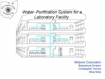
Water Purification System for a Laboratory Facility
Description:
Water Purification System for a Laboratory Facility Millipore Corporation Bioscience Division Christopher Yarima Mike Kelly Outline Contaminants in Water Pure Water ... – PowerPoint PPT presentation
Number of Views:581
Avg rating:5.0/5.0
Title: Water Purification System for a Laboratory Facility
1
Millipore CorporationBioscience
DivisionChristopher YarimaMike Kelly
- Water Purification System for a Laboratory
Facility
2
Outline
- Contaminants in Water
- Pure Water Applications and Quality Standards
- Water Purification Technologies
- Key Water Purification System Design Steps
Systems - Questions
3
Water Chemistry Contaminants
4
Ground Surface Water
5
Contaminants in Potable Water
Inorganic Ions Cations Na Ca2 Anions Cl- HCO-3
Organics Natural Tannic Acid Humic Acid Man Made Pesticides Herbicides
Particles (Colloids) Non Dissolved Solid Matter (Small deformable solids with a net negative charge) Non Dissolved Solid Matter (Small deformable solids with a net negative charge)
Microorganisms (Endotoxin) Bacteria , Algae , Microfungi (Lipopolysaccharide fragment of Gram negative bacterial cell wall) Bacteria , Algae , Microfungi (Lipopolysaccharide fragment of Gram negative bacterial cell wall)
6
Measurement of Contaminant level
7
Measurement Units
- Thickness of a Human hair 90 microns
- Smallest visible particle 40 microns
- 1 Micron 10-6 Meters
- Smallest bacteria 0.22 micron
- ppm Parts per Million mg/Liter
- ppb Parts per Billion microgram/Liter
- ppt Parts per Trillion nanogram/Liter
- 1 ppb 1 Second in 32 Years. !!!
8
Water Standards
9
Standards and Common Terms
Ultrapure/Reagent Grade Critical
Applications Water for HPLC,GC, HPLC ,AA ,
ICP-MS, for buffers and culture media for
mammalian cell culture IVF, reagents for
molecular biology...
Ultrapure
Type 1
Pure/Analytical Grade Standard Applications Buffer
s, pH solutions,culture media preparation
,clinical analysers and weatherometers feed.
Type II
Pure
Pure/Laboratory Grade General Applications Glasswa
re rinsing, heating baths, humidifiers and
autoclaves filling
Type III
10
Laboratory Water Purity SpecificationsConsolidate
d Guidelines
- Regulatory Agencies with Published Standards
- ASTM American Society for Testing and
Materials - CLSI Clinical and Laboratory Standards
Institute - (previously NCCLS National Committee for
Clinical Laboratory Standards) - CAP College of American Pathologists
- ISO International Organization for
Standardization - USP United States Pharmacopoeia
- EU European Pharmacopoeia
11
ASTM Standards for Laboratory Reagent Water
ASTM American Society for Testing and Materials
12
CLSI, water quality specifications CLSI
guidelines should be read to understand scope and
detail for each requirement
- CLRW Clinical Laboratory Reagent Water
- SRW Special Reagent Water
- CLRW water quality with additional quality
parameters and levels defined by the laboratory
to meet the requirements of a specific
application - For example CLRW quality with low silica and
CO2 levels - Instrument Feed Water
- Confirm use of CLRW quality with manufacturer
- Water quality must meet instrument manufacturers
specifications - Also defined
- Commercially bottled purified water, autoclave
and wash water and water supplied by a method
manufacturer (use as diluent or reagent)
CLSI Clinical and Laboratory Standards
Institute (previously NCCLS)
13
US and European Pharmacopoeia Pure Water
- Purified and Highly Purified Water
- USP Purified EU Purified EU
Highly Purified - Conductivity lt1.3 uS/cm at 25oC lt4.3
uS/cm at 20oC lt1.1 uS/cm at 20oC - TOC lt 500 ppb lt 500 ppb lt500 ppb
- Bacteria lt100 cfu/ml lt100 cfu/ml
lt10 cfu/100 ml - Endotoxin N/A N/A
lt0.25 EU/ml - Overview of USP28 and EP 4th edition, (refer to
detailed specifications for exact norms).
14
Purification Technologies
- Overview of Key Technologies
- Advantages/Disadvantages
- Summary
15
Purification Technologies
- Filtration Depth and Screen Filters
- Activated Carbon and chlorine removal
- Mineral scale control Softening and
Sequestering - Distillation
- Reverse Osmosis
- Deionization
- Electrodeionization
- Ultraviolet light
16
Depth Screen Filters
Glass Fiber SEM
Durapore Membrane - SEM
- Depth filters
- matrix of randomly oriented fibers in a maze of
flow channels.
- Screen filters
- rigid, uniform continuous mesh of polymeric
material with pore size precisely determined
during manufacture.
- 2 types of filters depth screen (or membrane)
filters. - Depth filters for RO protection from fouling
(high particle capacity). - Membrane filters for retention of small amounts
(quick clogging) of small particulates like
bacteria. - Additional treatment
- Depth filters for heavily loaded feed water
with particles (SDI over specification). - Screen filters for a final low pore size
filtration downstream the system. - Charge filters for pyrogen removal, in-line
distribution loop
17
Purification Technologies
- Filtration Summary
- Depth Filters
- Random Structure
- Nominal retention rating
- Works by entrapment within depths of filter
media - High dirt holding capacity
- Screen/Membrane Filters
- Uniform Structure
- Absolute retention rating
- Works largely by surface sieving
- Low dirt holding capacity
18
Activated Carbon
- Granules or beads of carbon activated to create a
highly porous structure with very high surface
area - Activation can be heat or chemical
- Pore sizes typically lt100 to 2000 Å
- Surface area typically 500 to gt2000 m2/gram
- Removal of organics by adsorption
- Removal of chlorine by adsorption-reduction
19
Mineral Scale Control
- Calcium and carbonate ions are common in tap
water supplies - Scale forms when concentration exceeds solubility
limits and CaCO3 precipitates as a solid - Higher concentrations increase risk of scale
formation - Higher pH and higher temperature increase risk of
scale formation - Important in domestic water systems and
purification technologies
20
Scale Control Ion-exchange Softening
"Hard water"
Cation Exchange Resin
Ca 2 Cl-
Mg 2 Cl-
Na
Na
R
R
Na
Na
R
R
Ca
R
R
R
R
Mg
4 Na 4 Cl-
"Soft water"
21
Scale ControlIon-exchange Softener Regeneration
Regenerated resin
Na
Na
R
R
Na
Cl-
Na
Na
R
R
Ca
R
R
conc. NaCl
Mg
R
R
Mg 2 CL-
Ca 2 Cl-
EXCESS Na Cl-
Exhausted resin
Softeners are regenerated using a concentrated
brine flush
22
Scale Control Chemical Sequestering
- Chemical sequestering weakly binds calcium ion
preventing calcium and carbonate ions from
forming scale - Liquid and solid chemical options available
- Solid polyphosphate shown as example illustration
Polyphosphate chain
23
Double Distillation Principal
- Benefits
- Removes wide class of contaminants
- Bacteria / pyrogen-free
- Low capital cost
- Limitations
- High maintenance
- High operating cost
- Low resistivity
- Organic carryover
- Low product flow
- High waste water flow
- Water storage
24
Natural Osmosis
- Pure water will pass though the membrane trying
to dilute the contaminants
Osmotic
Pressure
Water
Plus
Contaminants
Pure Water
Semi-Permeable
100 ppm NaCl 1 psi of osmotic pressure
Reverse Osmosis
Membrane
25
Reverse Osmosis
- Pressure applied in the reverse direction
exceeding the osmotic pressure will force pure
water through the membrane - A reject line is added to rinse contaminants to
drain
Pressure
Water
Plus
Pure Water
Contaminants
Semi-Permeable
Reject
Reverse Osmosis
Membrane
26
Reverse Osmosis Summary
- Limitations
- Not enough contaminants removed for Type II
water. - RO membrane sensitivity to plugging
(particulates), fouling (organic,colloids),
piercing (particle, chemical attack) and scaling
(CaCO3) in the long run if not properly
protected. - Need of right pressure (5 bars) right pH for
proper ion rejection. - Flow fluctuation with pressure and temperature.
- Membrane sensitivity to back pressure
- Preservative rinsing needed
- Need optimized reject
- Benefits
- All types of contaminants removed ions, organics
- pyrogens, viruses, bacteria, particulates
colloids. - Low operating costs due to low energy needs.
- Minimum maintenance (no strong acid or bases
cleaning) - Good control of operating parameters.
- Ideal protection for ion-exchange resin polisher
a large ionic part already removed (? resin
lifetime), particulates, organics, colloids also
eliminated (no fouling).
27
Ion Exchange
- Benefits
- Effective at removing ions
- ? Resistivity 1-10 M?.cm with a single pass
through the resin bed. - ? Resistivity 18 M?.cm with proper pretreatment
- Easy to use Simply open the tap and get water
- Low capital cost
- Limitations
- Limited or no removal of particles, colloids,
organics or microorganisms - Capacity related to flow rate and water ionic
content - Regeneration needed using strong acid and base
- Prone to organic fouling
- Multiple regenerations can result in resin
breakdown and water contamination - Risk of organic contamination from previous uses
28
Electrodeionization (EDI, CDI, ELIX, CIX)
Continuous deionization technique where mixed bed
ion-exchange resins, ion-exchange membranes and a
small DC electric current continuously remove
ions from water (commercialize by Millipore in
mid 80s)
Performance enhancements Ion-exchange added to
waste channels improve ion transfer and
removal. Conductive beads aded to cathode
electrode channel reduces risk of scale and use
of a softener
- Cations driven toward negative electrode by DC
current - Anions driven toward positive electrode by DC
current - Alternating anion permeable and cation permeable
membranes effectively separate ions from water - RO feed water Avoids plugging, fouling and
scaling of the EDI module
29
Electrodeionization
- Benefit
- Very efficient removal of ions and small MW
charged organic (Resitivity gt 5 M?-cm) - Low energy consumption
- Typical lt100 watt light bulb
- High water recovery
- No chemical regeneration
- Low operating cost
- Low maintenance
- No particulates or organic contamination (smooth,
continuous regeneration by weak electric current)
- Limitations
- Good feed water quality required to prevent
plugging and fouling of ion-exchange and scaling
at cathode electrode - RO feed water ideal
- New enhancements minimize risk of scale.
- Weakly charged ions more difficult to remove
- Dissolve CO2 and silica
- Moderate capital investment
30
UV Lamps (254 and 185 nm)
- UV energy catalyzes production of hydroxyl
radicals (OH). - These hydroxyl radicals generate reactions which
oxidize organic compounds. - As the oxidation of organics progresses, reaction
products become more polar (charged). - These charged species are removed by a special
ion exchange polishing cartridge
- The UV rays between 200 and 300 nm destroy the
micro-organisms by breaking the DNA chains. - The optimal wavelength for DNA damage is 260 nm.
- 254 nm radiation is quite close to the optimum
germicidal action efficiency (about 80) and can
therefore be successfully used to destroy
bacteria. - 254 UV does not oxidize organics
31
UV Technology (185 254 nm)
- Benefit
- Conversion of traces of organic contaminants to
charged species and ultimately CO2 (185 254) - Limited destruction of micro-organisms and
viruses (254) - Limited energy use
- Easy to operate
- Limitations
- Polishing technique only may be overwhelmed if
organic concentration in feed water is too high. - Organics are converted, not removed.
- Limited effect on other contaminants.
- Good design required for optimum performance.
32
Contaminant Removal Efficiency
Particulates
Inorganics
Organics
Bacteria
Reverse Osmosis
Ultrapure Ion Exchange
Electrodeionization
Carbon
Ultrafiltration
Microporous Filtration
2311BD10
33
Water Purification System DesignMulti-Step
Purification Process
Product Water
1
2
3
4
Type II
Type III
Low Bacteria
Tap water
34
Water Purification SystemOverview of Design
Considerations
35
Major phases in a project
- Definition of the needs
- Design of a total solution
- Budget estimation
- Tender (Bid) process
- Delivery of the units, accessories and
consumables - Installation
- Users training/Commissioning
- Additional phases
- Preventive maintenance
- Full support for validation
36
Major phases in a project
- Definition of the needs
- Design of a total solution
- Budget estimation
- Tender (Bid) process
- Delivery of the units, accessories and
consumables - Installation
- Users training/Commissioning
- Additional phases
- Preventive maintenance
- Full support for validation
37
Design ProcessKey Steps
- Define the pure water requirements and
specifications - Design the distribution loop
- Design the makeup system and storage tank
- Review and Finalize specifications and design
38
Design Process Step 1
1
- Defining the pure water requirements and
specifications - What purity level?
- How much water?
- When is it needed?
- Where is it needed?
39
Defining the pure water requirements and
specifications
1
- What purity level?
- What labs and locations need purified water?
- What kind of work will be carried out in each
lab, at each location? - General rinsing/washing to sensitive trace
analysis,? - Are there instruments that will need pure water?
- Glassware washers, steam sterilizers,
autoclaves..? - Are there any maximum purity level
requirements? - What water quality is needed for each location?
- Ionic, Organic, and Microbiological Quality?
- Are there alert and action levels?
- Are there standard specifications to follow?
- How much water? When? Where?
40
Definition of the needsQuestions to select the
right configuration and design
1
- What purity level?
- How much water? When? Where?
- How much water is needed each day?
- In each lab, at each location,..?
- By the individual users, instruments, ultrapure
polishing systems? - How is the demand distributed during the day?
- Steady demand over the course of a day?
- Peak demands at certain times of the day?
- How many floors need water?
- Where is each location?
- Are there remote locations that need water?
- What are the distances between each location?
41
1
Defining the pure water requirements and
specifications
- What purity level?
- How much water? When? Where?
- Additional questions
- Does the equipment need to be validated?
- At all locations?
- Who will do the maintenance?
- Is a service/maintenance contact required?
- Are the water quality requirements similar
between locations? - How many researchers/scientists will work in each
lab? - Where can the equipment be located (space)?
- Where can piping be run?
- Are there plans for future expansion?
42
Step 2 Designing the Distribution Loop
2
- Define the distribution piping
- Design Layout
- Materials, welding method, valve type, pipe
diameter - Design Considerations
- Define Loop Purification and Monitoring Equipment
- Determine distribution pump performance
- Flow rate and pressure
43
2
Distribution Loop Layout OptionsGravity Feed
44
2
Distribution Loop Layout OptionsSingle Loop and
make-up system Central Location
45
2
Distribution Loop Layout OptionsSingle Loop and
Duplex-central make-up system
46
2
Distribution Loop Layout OptionsMultiple Loop
and make-up systems
47
2
Distribution Loop Layout OptionsMultiple Loop
and make-up systems and POU systems
48
Design Considerations Avoid Dead legs
2
- 6D rule CFR212 regulations of 1976
- Good Engineering practice requires minimizing
the length of dead legs and there are many good
instrument and valve designs available to do so.
6D rule
- 0.59
- Maximum dead leg 6 times the pipe diameter
- 0.59 X 6 3.5
- Maximum dead length of 3.5 inches
Maximum length 6X pipe diameter (our example max
is 3.5 inches)
49
Design Considerations Avoid Dead legs
2
- 2D rule ASME Bioprocessing Equipment Guide of
1997 - Good Engineering practice requires minimizing
the length of dead legs and there are many good
instrument and valve designs available to do so.
- Maximum dead leg 2 times the pipe diameter
Example
- 0.59 X 2 1.2
- Maximum dead length of 1.2 inches
50
Design Considerations Flow Velocity
2
- Design system for 3 to 5 f/s (1 to 1.5 m/s) to
- Maintain turbulent flow
- Minimize biofilm on internal walls
- Balance between velocity and pressure drop
- Higher velocity results in too high a pressure
drop - Requiring a larger pump and risk of increased
water temperature
51
Design Considerations Flow Velocity
2
Velocity through distribution pipe 3 to 5 ft/sec
design target, (1 to 1.5 m/s)
52
Define Loop Purification and Monitoring Equipment
2
- Loop purification equipment to maintain water
quality - UV lamp
- Bacteria control
- TOC Reduction
- Filtration
- Membranes for Bacteria and particle control
- Ultra-filtration for Pyrogen removal
- Deionization Ion removal
- Loop Water Purity Monitoring
- Resistivity
- TOC
- Bacteria
- Temperature
- Sanitant Monitors (Ozone)
53
Loop Monitoring
2
Sanitary Sampling Valve
54
Loop Bacteria Sampling
2
Sanitary Sampling Valve
- Designed for sanitary sampling (bacteria and
endotoxin) - Mid-stream sampling
- Zero-Dead leg when closed
- Sanitize easily in place
- Direct attachment to samplers
55
Determine the Distribution Pump Requirements
2
- Pump selection is based on flow rate and pressure
requirements - Flow rate required defined in step 1
- Pressure requirement
- Total Pressure requirement can be estimated by
adding - piping pressure loss
- loop equipment pressure loss
- pressure due to elevation changes
- pressure required at furthest point of use (25
psi typical) - Select a pump that delivers the required flow
rate and pressure - Reduce pressure loss by increasing pipe diameter,
(keeping balance with flow required and target
velocity) - For added reliability a duplex pumping system can
be used
56
Distribution SystemsWater Flow Dynamics
Pressure drop
2
- Pressure drop through pipe the resistance to
water flow moving through a pipe - (friction losses occurring along pipe walls and
through fittings and valves) - Key factors influencing pressure drop
- Pipe material, (surface roughness)
- Pipe diameter
- Pipe length
- Flow rate
- Determining pressure drop through pipe
- Hazen-Williams formula for predicting pressure
drop, (turbulent flow) - Simplified
- Hp 0.000425 (L) x (Q)1.85/(d)4.86
- Hp pressure drop in psi
- L pipe length in feet
- Q flow in GPM
- d pipe inside diameter
- (friction factor included for smooth surfaces)
57
Distribution SystemsWater Flow Dynamics
Pressure drop
2
- Determining pressure drop through fittings
- Fittings (elbows, tees, unions, etc..)
- Flow through fittings creates turbulence and adds
to pressure drop - Equivalent pipe length method most common
- Express each fitting as a length of pipe
Example 2 ft 1 ft (1) 90o elbow 90o elbow
2 equivalent feet of pipe 2 1 2 eq-ft 5
feet total length
58
Distribution SystemsWater Flow Dynamics
Pressure drop
2
- Determining pressure drop through additional loop
equipment - Refer to manufacturers specifications
- UV lamps Typically 2 to 3 psi
- Filters and housings
- Pressure loss data
20 inch Code-0 Durapore
59
Determine the Distribution Pump Requirements
2
- Example worksheet tool
- Helps track and automatically calculate all key
parameters - Sizing and selection of correct pump is a key
step in the design process
60
Determine the Distribution Pump Requirements
2
- Pump performance curve
- 15 GPM and 180 feet of head (78 psi) shown as an
example - Select the pump that meets the minimum
requirements
61
Step 3 - Design the Makeup Purification System
and Storage Tank
3
- Select the make-up purification system to match
the water quality required - Size the makeup purification system to match the
quantity required per day - Size the storage tank to meet peak demands during
the day - Determine the pretreatment needed
62
Makeup System Sizing and Quality
3
- Match to the quality requirement (defined in step
1) - RO/EDI or RO/DI system for Type 2 pure water
applications - RO system for Type 3 more general applications
- Size the makeup system to match the quantity
required per day (defined in step 1) - Plans for future expansion?
- Are Duplex systems needed?
- Back-up for maintenance-down time.
- Option to add for future expansion
63
Sizing Makeup System and Tank
3
Sizing the makeup system is done in conjunction
with the storage tank Sizing Examples
- Company A needs water to clean vessels in the
first two hours of the day shift. They need a
total of 1200 Gallons in two hours. - 1500 Gallon Tank with 100 gph make-up rate
- Company B needs pure water to feed automated
Filling machine. They need 200 gallons per hour
for an 8 hour shift. - 200 Gallon Tank with 200 gph make-up rate
64
Determine the pretreatment needed for the makeup
water system
3
- Determine feed flow rate base on the make-up
system water recovery rate - Feed Flow Rate RO Product / RO recovery rate
- Complete feed water analysis
- conductivity, chlorine, fouling index, pH,
hardness, alkalinity.. - Select pretreatment options based on feed water
analysis and manufacturers recommendations - Multimedia Sand Particulate contamination
- Carbon Filters Chlorine and some organic
removal - Softeners Hard water (Mg or Ca
contamination) - Cartridge Filters Particulate and carbon
options
65
Design Process Step 4
4
- Step 4 - Finalize Design
- Prepare Process Flow Diagram (PFD), supporting
documents and specifications - Design Controls and Monitoring
- Review Validation requirements
- Review who will maintain the equipment
- Consider service/maintenance plans
- Review requirements, specifications, design,
equipment and PFD with customer/client - Update and Finalize design as needed
66
Outline
- Contaminants in Water
- Pure Water Applications and Quality Standards
- Water Purification Technologies
- Key Water Purification System Design Steps
Systems - Questions ???
67
Millipore CorporationBioscience
DivisionChristopher YarimaMike Kelly
- Water Purification System for a Laboratory
Facility - Thank You!!
Recommended
CrystalGraphics Presentations


