
Selective Repeat (SR) ACK Scheme - PowerPoint PPT Presentation
1 / 131
Title:
Selective Repeat (SR) ACK Scheme
Description:
... QoS capabilities Extensible option system Improved Mobile IP capabilities Modified dynamic routing protocols for IPv6 MP-BGP4+, ... IPv6 - the Technology ... – PowerPoint PPT presentation
Number of Views:11
Avg rating:3.0/5.0
Title: Selective Repeat (SR) ACK Scheme
1
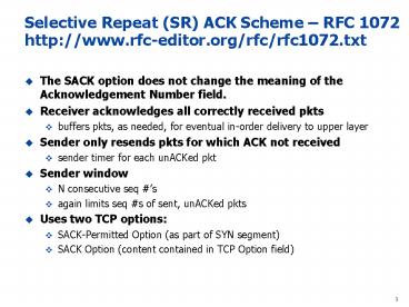
Selective Repeat (SR) ACK Scheme RFC 1072
http//www.rfc-editor.org/rfc/rfc1072.txt
- The SACK option does not change the meaning of
the Acknowledgement Number field. - Receiver acknowledges all correctly received pkts
- buffers pkts, as needed, for eventual in-order
delivery to upper layer - Sender only resends pkts for which ACK not
received - sender timer for each unACKed pkt
- Sender window
- N consecutive seq s
- again limits seq s of sent, unACKed pkts
- Uses two TCP options
- SACK-Permitted Option (as part of SYN segment)
- SACK Option (content contained in TCP Option
field)
2
How SACK Option Is Exchanged Between Sender and
Receiver Using the TCP Option Field
The 2-byte TCP Sack-Permitted option may be sent in a SYN by a TCP that has been extended to receive (and presumably process) the SACK option once the connection has opened. It MUST NOT be sent on non-SYN segments. The SACK option is to be used to convey extended acknowledgment information from the receiver to the sender over an established TCP connection.
- The 2-byte TCP Sack-Permitted option may be sent
in a SYN by a TCP that has been extended to
receive (and presumably process) the SACK option
once the connection has opened. It MUST NOT be
sent on non-SYN segments. The SACK option is to
be used to convey extended acknowledgment
information from the receiver to the sender over
an established TCP connection.
3
How TCP SACK Handles Non-Contiguous TCP Segments
at the Receiver
The 2-byte TCP Sack-Permitted option may be sent in a SYN by a TCP that has been extended to receive (and presumably process) the SACK option once the connection has opened. It MUST NOT be sent on non-SYN segments. The SACK option is to be used to convey extended acknowledgment information from the receiver to the sender over an established TCP connection.
The 2-byte TCP Sack-Permitted option may be sent in a SYN by a TCP that has been extended to receive (and presumably process) the SACK option once the connection has opened. It MUST NOT be sent on non-SYN segments. The SACK option is to be used to convey extended acknowledgment information from the receiver to the sender over an established TCP connection.
The 2-byte TCP Sack-Permitted option may be sent in a SYN by a TCP that has been extended to receive (and presumably process) the SACK option once the connection has opened. It MUST NOT be sent on non-SYN segments. The SACK option is to be used to convey extended acknowledgment information from the receiver to the sender over an established TCP connection.
- The SACK option is to be sent by a data receiver
to inform the data sender of non-contiguous
blocks of data that have been received and
queued. The data receiver awaits the receipt of
data to fill the gaps in sequence space between
received blocks. When missing segments are
received, the data receiver acknowledges the data
normally by advancing the left window edge in the
Acknowledgement Number Field of the TCP header.
The SACK option does not change the meaning of
the Acknowledgement Number field. - Left Edge of Block This is the first sequence
number of this block. - Right Edge of Block This is the sequence number
immediately following the last sequence number of
this block.
4
How Selective-Repeat ACK Works
- The recovery of a corrupted PDU proceeds in four
stages - First, the corrupted PDU is discarded at the
remote node's receiver. - Second, the remote node requests retransmission
of the missing PDU using a control PDU (sometimes
called a Selective Reject). The receiver then
stores all out-of-sequence PDUs in the receive
buffer until the requested PDU has been
retransmitted. - The sender receives the retransmission request
and then transmits the lost PDU(s). - The receiver forwards the retransmitted PDU, and
all subsequent in-sequence PDUs which are held in
the receive buffer.
5
Selective Repeat In Action
6
Selective Repeat Sender, Receiver Windows
7
How Is The Destination TCP Buffer Affected by the
Selective-Repeat Scheme?
- Operation of Selective Repeat The sender
transmits four PDUs (1-4). The first PDU (1) is
corrupted and not received. The receiver detects
this when it receives PDU(2), which it stores in
the receive buffer and requests a selective
repeat of PDU(1). The sender responds to the
request by sending PDU(1), and then continues
sending PDUs (5-7). The receiver stores all
subsequent out-of-sequence PDUs (3-4), until it
receives PDU(1) correctly. The received PDU (1)
and all stored PDUs (2-4) are then forwarded,
followed by (5-7) as each of these is received in
turn
8
Sliding Window ProtocolsGo-back-N and Selective
Repeat
Go-back-n Selective Repeat
data bandwidth sender to receiver(avg. number of times a pkt is transmitted) Less efficient More efficient
ACK bandwidth (receiver to sender) More efficient Less Efficient
Buffer size at receiver 1 W
Complexity Simpler More complex
p the loss rate of a packet M number of seq
(e.g., 3 bit M 8) W window size
9
TCP Multiplexing
- Many programs will use a separate TCP connection
as well as a UDP connection
10
TCP Multiplexing
- By specifying ports and including port numbers
with TCP/UDP data, multiplexing is achieved - Multiplexing allows multiple network connections
to take place simultaneously - The port numbers, along with the source and
destination addresses for the data, determine a
socket
11
(No Transcript)
12
Advanced TopicMPLS Switching/Routing
13
Concept of Traffic Engineering (TE)
- Concerns with the performance optimization of
operational networks - This concern was due to the fact that IGP routing
always selects least-cost path from source to
destination that can lead to over-utilized and
under-utilized links - Need a tool that allows us to steer traffic so
that can lead to more balanced flow of traffic
across links based - MPLS
14
Pros and Cons of the TCP/IP Model
- Pros
- The layering and encapsulating concept is useful
by breaking out larger problems into smaller
manageable layers - The layering model is logical and therefore
provides opportunity for technology adaptation
(sub-layering) - Cons
- Data encapsulation can reduce throughput and
efficiency of each layer because they are not
aware of the packetization process that happens
in the lower layers - Tweaking TCP window size and MTU size is a
challenge in real life - The TCP and IP packet formats do not lend
themselves to strong security - SSL and IPSec had to be added later to solve this
problem
15
A Motivation For MPLS - The Hyper-Aggregation
Problem
Traffic for Washington SPF routed
many under-utilized links 4 over-utilized links
Washington
San Jose
MASSIVE CONGESTION
CONGESTION
16
How Is MPLS Used?
- One of the primary original goals of MPLS,
boosting the performance of software-based IP
routers, has been superseded as advances in
silicon technology have enabled line-rate routing
performance implemented in router hardware. - In the meantime, additional benefits of MPLS have
been realized, notably VPN services (layer 2 or
layer 3) and traffic engineering.
17
Network Engineering and Traffic Engineering
- Network Engineering
- "Put the bandwidth where the traffic is"
- physical cable deployment
- virtual connection provisioning
- Traffic Engineering
- "Put the traffic where the bandwidth is"
- on-line or off-line optimisation of routes
- route diversify
18
Network Engineering Adds Bandwidth
1
Washington
San Jose
2
1
1
1
IGP Metrics
- Mechanisms
- bandwidth over-provisioning
- metric manipulation
- Limitations
- some links become under-utilized or over-utilized
- trial-and-error approach
- expensive
19
Traffic Engineering Distributes Traffic
TE-distributed traffic over the network resources
Washington
San Jose
20
MPLS MultiProtocol Label Switching
- MPLS is not a routing protocol it works with
layer 3 routing protocols (BGP, IS-IS, OSPF) to
integrate network layer routing with label
switching. - Not just QoS A way to set up connections and
treat the connection in a certain way - Traffic Engineering steer it this way
- QoS is another way this connection should be
treated - Establish a Forwarding Equivalence Class (FEC) at
the ingress, and map the IP packets to the FEC - An FEC represents a group of packets that share
the same requirements for their transport (Delay,
Jitter, Packet Loss, etc) - The FEC has a label value a fixed value, no
mask (like IP destinations) - Once the label is assigned, packets are forwarded
(switched) according to the label and not the
destination IP address - Faster lookups on fixed-length values than on
variable-length values - Very similar to ATM and Frame Relay switching
- Runs over layer 2 vs RSVP which runs over layer 3
- More secure
- MPLS Operating Planes
- Data Plane label swapping and forwarding
labeled packets - Control Plane routing, signaling and control
protocols that assign lables to IP
routes/prefixes - Existing protocols Label Distribution Protocol
(LDP) or RSVP-TE - Think of an LDP as being an official way for one
LSR to say to another "let's use this label to
get stuff to this destination really fast".
21
MPLS Shim Header Format
Label bitsTwenty bits EXP bitsThree bits
for class of service information these bits are
variously called the experimental bits,
class of service (CoS) bits, or type of service
(ToS) bits. The EXP bits are mapped from the
IP packet at the ingress node and are mapped back
into the IP packet at the egress node. S
bitOne bit to indicate whether the label is on
the bottom of the label stack. TTL bits-Eight
bits for a time-to-live indicator. The TTL bits
are mapped from the IP packet at the ingress
node. The TTL bits in the shim header are
decremented at each hop.
22
Data Flow In An MPLS Network
23
MPLS Architecture
- As packets enter the MPLS network, they are
mapped to labels based on their destination IP
addresses - Routers that run MPLS are known as Label
Switching Routers (LSRs) - The MLPS connection is called a Label-Switched
Path (LSP) - All packets going to a single destination with
similar characteristics (e.g., QoS) belong to the
same Forwarding Equivalence Class (FEC)
24
Forward Equivalent Class (FEC) What it means
- A Forwarding Equivalence Class (FEC) is a class
of packets that should be forwarded in the same
manner (i.e. over the same path). - A FEC is not a packet, nor is it a label. A FEC
is a logical entity created by the router to
represent a class (category) of packets. When a
packet arrives at the ingress router of an MPLS
domain, the router parses the packet's headers,
and checks to see if the packet matches a known
FEC (class). Once the matching FEC is determined,
the path and outgoing label assigned to that FEC
are used to forward the packet. - FECs are typically created based on the IP
destinations known to the router, so for each
different destination a router might create a
different FEC, or if a router is doing
aggregation, it might represent multiple
destinations with a single FEC (for example, if
those destinations are reachable through the same
immediate next hop anyway). The MPLS framework,
however, allows for the creation of FECs using
advanced criteria like source and destination
address pairs, destination address and TOS, etc.
25
Forwarding Equivalence Class (FEC)
- Introduced in MPLS standards to denote packet
forwarding classes - Comprises traffic
- to a particular destination
- to destination with distinct service
requirements - Why FEC?
- To precisely specify which IP packets are mapped
to each LSP - Done by providing a FEC specification for each
LSP
26
Forward Equivalent Class (FEC) Classification
- A packet can be mapped to a particular FEC based
on the following criteria - destination IP address,
- source IP address,
- TCP/UDP port,
- class of service (CoS) or type of service (ToS),
- application used,
- any combination of the previous criteria.
27
FEC Concept Assigning a label with an incoming
FEC using IP header info
28
IP Routing With Routing Table
B.0
Z
2
Z
Z
Z.0
1
3
1
2
A.0
C.0
R2
R1
Dest.
Next Hop
Cost
Port
Dest.
Next Hop
Cost
Port
A.0
direct
0
1
A.0
R1
1
1
B.0
direct
0
2
B.0
R1
1
1
C.0
direct
0
3
C.0
direct
0
1
Z.0
R2
1
3
Z.0
direct
0
2
29
Routing with MPLS Label Forwarding Information
Base (LFIB)
Router Incoming Label Incoming Interface Destination Network (FEC) Outgoing Interface Outgoing Label
R1 --- E0 172.16.1.0 S1 6
R2 6 S0 172.16.1.0 S2 11
R3 11 S0 172.16.1.0 S3 7
R4 7 S1 172.26.1.0 E0 --
Q create LFIB for R4 gt R3 gt R2 gt R1
30
Routing Comparisons - IP and MPLS
IP Network
Access Link
Router
Washington
Router
Router
San Jose
Customer Site-B
Customer Site-A
Router
MPLS Network
LSP
E-LER
Washington
I-LER
LSR
San Jose
Customer Site-B
Customer Site-A
LSR
31
MPLS Technology Map
E-LER
Washington
I-LER
LSR
San Jose
LSR
LSP
- LSR Label Switching Routers - routers or
switches that handle MPLS and IP traffic they
swap labels - LER Label Edge Routers - LSRs at the edge of
MPLS networks - I-LER Ingress LERs - classify unlabeled IP
packets and push labels - E-LER Egress LERs - pop labels and route
unlabeled IP packets - LSP Label Switched Paths - path between I-LER
and E-LER created by MPLS LSPs are always
uni-directional
32
Actions at LERs and LSRs
- Ingress _at_ I-LER
- PUSH the label assign the traffic to an LSP or
get on the LSP here - Transit _at_ LSRs
- SWAP the label switch the packet according to
label info - Exact-match versus longest-match
- Egress _at_ E-LER
- POP the label at the end of the LSP, strip the
label - Penultimate Hop Popping
- Cheat strip the label at the second-to-last
router - This is done by the E-LSR send a label value of 3
to the penultimate Router - Helps offload the processing done by the E-LER
33
Data Flow in an MPLS Networks - LERs
Much like the mail room that classifies mail to
your branch location into routine, priority and
overnight mail, the Label Edge Router classifies
traffic. In MPLS, this classification process is
called forward equivalence class, or FEC for
short. The LER are the big decision points. LER
are responsible for classifying incoming IP
traffic and relating the traffic to the
appropriate label. This traffic classification
process is called the FEC (Forward Equivalence
Class). LER use several different modes to label
traffic. In the simplest example, the IP
packets are nailed up to a label and an FEC
using preprogrammed tables such as the example
shown in table below.
The LER are the big decision points. LER are
responsible for classifying incoming IP traffic
and relating the traffic to the appropriate
label. This traffic classification process is
called the FEC (Forward Equivalence Class).
34
LER Instruction Set
Destination / IP Port Number FEC Next Hop Label Instruction
199.50.5.1 80 B x.x.x.x. 80 Push
199.50.5.1 443 A y.y.y.y 17 Push
199.50.5.1 25 IP z.z.z.z (Do nothing native IP)
35
MPLS LSRs
The function of LSR is to examine incoming
packets. Providing that a label is present, the
LSR will look up and follow the label
instructions, and then forward the packet
according to the instructions. In general, the
LSR performs a label swapping function
36
LSRs Label Information Base (LIB)
Label/In Port In Label/Out Port/Out FEC Instruction Next Hop
80 B 40 B B Swap
17 A 18 C A Swap
37
MPLS LSP
LSP established between MPLS-aware devices.
Because MPLS works as an overlay Protocol to
IP, the two protocols can co-exist in the same
cloud without interference.
38
FECs and Labels
39
Label Assignment and Distribution
- Labels are locally significant can be switched
at each leg of the connection - Downstream router assigns label to upstream
router - Header and label formats Figure 8-19
- Header is 32 bits, including 20 bits of label, 3
bits of CoS - Protocols to distribute labels between routers
RSVP and LDP - Multiple labels in a Label Stack
40
L3 VPN
L3 VPNs. MPLS VPNs fall into two broad classes
those that operate at Layer 3 and those that
operate at Layer 2. Layer 3 VPNs were first to be
investigated and standardized in RFCs. Layer 3
VPNs based on RFC 2547bis have seen the most
widespread deployment to date. RFC
2547bis-based Layer 3 VPNs use extensions to BGP,
specifically Multi-Protocol internal BGP
(MP-iBGP), to distribute VPN routing information
across the provider backbone. Standard MPLS
mechanisms (as previously discussed) are used to
forward the VPN traffic across the backbone. In
an L3 VPN, the CE and PE routers are IP routing
peers. The CE router provides the PE router with
the routing information for the customer's
private network behind it. The PE router stores
this private routing information in a Virtual
Routing and Forwarding (VRF) table each VRF is
essentially a private IP network. The PE router
maintains a separate VRF table for each VPN,
thereby providing appropriate isolation and
security. VPN users have access only to sites or
hosts within the same VPN. In addition to the VRF
tables, the PE router also stores the normal
routing information it needs to send traffic over
the public Internet.
L3 VPNs use a two-level MPLS label stack (see
Figure 3). The inner label carries VPN-specific
information from PE to PE. The outer label
carries the hop-by-hop MPLS forwarding
information. The P routers in the MPLS network
only read and swap the outer label as the packet
passes through the network. They do not read or
act upon the inner VPN label that information is
tunneled across the network. The L3 VPN
approach has several advantages. The customer IP
address space is managed by the carrier,
significantly simplifying the customer IT role as
new customer VPN sites are easily connected and
managed by the provider. L3 VPNs also have the
advantage of supporting auto-discovery by
leveraging the dynamic routing capabilities of
BGP to distribute VPN routes. The Layer 3
approach has disadvantages as well. Layer 3 VPNs
support only IP or IP-encapsulated customer
traffic. Scaling also can be a significant issue
with PE routers required to support BGP routing
tables that are larger than normal with the
addition of the VPN routes.
41
An MPLS LSPs Used as Tunnels
42
An MPLS LSPs Used as Tunnels
43
Example of How Labels Are Mapped
1. Label Request
Label Request ltLSR2, LSR3, LSR4gt
Label Request ltLSR4gt
Label Request ltLSR3, LSR4gt
B
A
Label Mapping lt32gt
Label Mapping lt17gt
Label Mapping lt24gt
2. Label Mapping
44
LSPs for Different Traffic Types
Image taken from Voice over IP Solutions, Juniper
Networks, June 2001
45
Advanced Topic IP Sec
46
Network Security 101
- Integrity Received Sent
- Availability Legal users should be able to use
system. Ping - Confidentiality No wiretapping and snooping
- Authentication You are who you say you are
- Authorization Access Control
47
Cryptographic Methods - Secret Key (symmetric)
Cryptography
- A single key is used to both encrypt and decrypt
a message. A secure channel must be in place for
users to exchange this common key.
Plaintext Message
48
Alternate Way to Provide Symmetric Cryptography -
Hash Functions
In cryptography, a cryptographic hash function is
a hash function with certain additional security
properties to make it suitable for use as a
primitive in various information security
applications, such as authentication and message
integrity. A hash function takes a long string
(or message) of any length as input and produces
a fixed length string as output, sometimes termed
a message digest or a digital fingerprint.
A hash function at work
49
Authentication Using Hash Functions
50
Cryptographic Methods- Public Key (asymmetric)
Cryptography
- Two keys are used for this method, the public key
is used to encrypt. The private key is used to
decrypt. This is used when it isnt feasible to
securely exchange keys.
51
Cryptographic Methods - Public Key Cryptography
52
Public-key Cryptosystem Two Modes of Operation
Bs PUBLIC Key
Bs PRIVATE Key
Provides Confidentiality, Data Integrity
Plaintext
Plaintext
A Encrypt
B Decrypt
Ciphertext
Encryption Mode
As PRIVATE Key
As PUBLIC Key
Provides Data Origin Authentication, Data
Integrity
Plaintext
Plaintext
A Encrypt
B Decrypt
Ciphertext
Authentication Mode
53
Purpose of IPSec
- IPSec provides a secured mechanism to send data
over unsecured infrastructure using secure
tunnels between two peers, such as two routers.
You define which packets are considered sensitive
and should be sent through these secure tunnels,
and you define the parameters which should be
used to protect these sensitive packets, by
specifying characteristics of these tunnels.
Then, when the IPSec peer sees such a sensitive
packet, it sets up the appropriate secure tunnel
and sends the packet through the tunnel to the
remote peer. - Provides security for transmission of sensitive
information over UNPROTECTED networks such as the
Internet - Acts at the network layer, protecting and
authenticating IP packets between IPSec devises
(peers) - Services provided by IPSec
- Data Confidentiality
- Encrypts packets before sendint them across a
network - Data Integrity/Authentication
- The IPSec receiver can authenticate packets sent
by the IPSec sender to ensure that the data has
not been altered during transmission - Data origin Authentication
- The IPSec receiver can authenticate the source of
the IPSec packets sent. This service is dependent
upon the data intergrity service - Anti-Replay
- The IPSec receiver can detect and reject replayed
packets
54
Concept of IPSec
- IPsec is a set of extensions to the IP protocol
family. It provides cryptographic security
services. These services allow for - authentication, integrity, access control, and
confidentiality. - IPsec provides similar services as SSL, but at
the network layer, in a way that is completely
transparent to your applications, and much more
powerful. We say this because your applications
do not have to have any knowledge of IPsec to be
able to use it. You can use any IP protocol over
IPsec. You can create encrypted tunnels (VPNs),
or just do encryption between computers. Since
you have so many options, IPsec is rather complex
(much more so than SSL!) - IPsec works in any of these three ways
- Host-to-Host ( VPNs)
- Host-to-Network (VPNs)
- Network-to-Network (Tunneling)
55
How IPSec Uses Over TCP/IP
- IPSec protocol uses UDP Port 500 to first
authenticate and exchange keys prior to session
(Key Exchange) - Subsequently, IPSec protocol uses IP service 50
and 51 to transfer encrypted data (Tunneling) - Being used frequently to remotely login to
corporate network via unsecured Internet
56
What are the protocols behind IPsec?
- IPsec IKE AH ESP
- IKE AH and ESP need shared secret key between
peers. For communication between distant
location, we need to provide ways to negotiate
keys in secrecy. IKE will make it possible. - IPsec provides confidentiality, integrity,
authenticity, and replay protection through two
new protocols. These protocols are called
Authentication Header (AH), and Encapsulating
Security Payload (ESP). - AH provides authentication, integrity, and replay
protection (but not confidentiality). The main
difference between the authentication features of
AH and ESP is that AH also authenticates portions
of the IP header of the packet (such as the
source/destination addresses). ESP authenticates
only the packet payload. - ESP can provide authentication, integrity, replay
protection, and confidentiality of the data (it
secures everything in the packet that follows the
header). Replay protection requires
authentication and integrity (these two go always
together). Confidentiality (encryption) can be
used with or without authentication/integrity.
Similarly, one could use authentication/integrity
with or without confidentiality. In practice, it
is recommended that ESP be used for most
applications.
57
IKE Internet Key Exchange in IPSec
- IPsec uses the concept of point-to-point peers.
These peers share Transform Sets (TS) with each
other during the Security Association negotiation
process, and these Transform Sets determine the
character of the IPsec session that they share. A
Transform Set consists of the following
information - The IPsec security protocol (AH or ESP)
- Integrity/Authority algorithm (MD5, SHA-1)
- Encryption Algorithm (DES, 3-DES)
- There are basically 3 steps involved
- Specific algorithms and hashes used to actually
secure the communications are agreed upon - A Diffie-Hellman exchange takes place, which is
used to generate shared secret keys. This is used
to verify the identity of both end points in step
three. - Based upon the IP address of both end points the
identity of each other is verified. The earlier
noted key exchange is now used to decrypt the IP
addresses thereby verifying them. - Peers may be from different manufacturers, so
they use this negotiation process to work out the
lowest common denominator with regards to the
features that the peers have been configured to
use. Bear in mind that these transform sets are
configurable and operate on a session by session
basis and they do not necessarily represent the
full capabilities of the device. You may for
instance configure a different transform set for
one connection compared to a transform set for
another connection.
58
Internet Key Exchange (IKE) - Algorithm
Diffie Hellman Key Exchange Assume there are 2
entities (in this case applets), A and B. A owns
a private value (an integer), x, while B owns the
private integer y. A and B mutually agree on 2
parameters, p g. Consequently A is able to
generate a value e where efunction(x,p,g) and
similarly B generates f where ffunction(y,p,g).
A exports the value e to B and B exports f to A.
Thus e f are public while x y remain private.
As the illustration below shows, the secret keys
k k' are each generated privately by A and B
respectively, but due to the nature of their
derivation, both k k' are equivalent, allowing
A and B to use them as the secret key in a
symmetric cipher.
59
AH Header Format
The format of an Authentication Header is shown
in Figure 1. The first field in the AH is the
next header field this is an 8-bit field that
tells which higher-level protocol (such as UDP,
TCP, or ESP) follows the AH. The payload length
is an 8-bit value that indicates the length of
the authentication data field in 32-bit words.
The reserved area is a 16-bit field that's not
currently in use this field has been set aside
for future use, and therefore is always set to
zero. The Security Parameters Index (SPI) and
the sequence number fields come next. SPI is a
32-bit number that tells the packet recipient
which security protocols the sender is using.
This information includes which algorithms and
keys are being applied by the sending device.
The sequence number tells how many packets with
the same parameters have been sent. This number
acts as a counter and is incremented each time a
packet with the same SPI is bound for the same
address. The sequence number also guards against
a potential attack where a packet is copied and
then sent out to confuse the sender and
receiver. At the end of the AH is the
authentication data, which is a digital signature
for the packet. To authenticate users, the AH
can use either RSA Data Security's Message Digest
5 algorithm or the U.S. government's Secure Hash
Algorithm. The IETF is also looking into other
authentication algorithms, such as hashed message
authentication code.
60
ESP Header Format
As shown in Figure 2, the ESP includes several
parts, the first of which is the control header
that contains the SPI and the sequence number
field. The SPI and sequence number serve the same
purpose as in the AH. The SPI indicates which
security algorithms and keys were used for a
particular connection, and the sequence number
keeps track of the order in which packets are
transmitted. The SPI and sequence number are
not encrypted, but they are authenticated. The
next few parts of the ESP are encrypted during
network transmission. The payload data contains
info on security data used for encryption and can
be of any size (subject to the normal limits of
IP) because it's the actual data being carried by
the packet. Along with the payload data, the ESP
also contains 0 bytes to 255 bytes of padding,
which ensures the data will be of the correct
length for particular types of encryption
algorithms. This area of the ESP also includes
the pad length, which tells how much padding is
in the payload, and the next header field, which
gives information about the data and the protocol
used. The last piece is the optional
authentication data. This field contains a
digital signature that has been applied to
everything in the ESP except the authentication
data itself. To decide whether ESP or AH is best,
network managers or security officers need to ask
whether they only need authentication or if they
need both authentication and encryption. Because
AH doesn't provide encryption capabilities, if a
scenario requires both features, ideally ESP
makes better sense since it does offer both
authentication and encryption.
61
ESP Header - Example
ESP(spi0x14579c09,seq0x4926) (ttl
243, id 9712, len 1072)0x0000 4500 0430 25f0
0000 f332 94e8 c0a8 0164
E..0....2.....0x0010 c0a8 01c8 1457 9c09
0000 4926 67f3 2e95 .....W....Ig...0x0020
6804 f49a a7e6 e6c5 4fd8 7b7a c2b0 1575
h.......O.z...u0x0030 dbdd a425 2d73 9565
0b13 0273 53dc c6b3 ...-s.e...sS...0x0040
9301 eb2b 3d29 f85e 2b81 799c ec07 1e80
...)..y.....0x0050 08fb cf16 9cea 3263
3d46 55f6 f070 a6f0 ......2cFU..p.0x0060
4029 0453 4707 19cc 0212 5d33 36fa 134a
_at_).SG.....36..J0x0070 d640 690c 01f6 ac9c
3818 1da5 becb 2baa ._at_i.....8......
62
IPSec Modes of Operation
- Transport Mode (Less secured) Encrypts normal
communication between peers with routing info
untouched (IP Address) - only the payload (data) of the original IP packet
is protected (encrypted, authenticated, or both)
and not the end-to-end header. - The payload is encapsulated by the IPSec
headers and trailers (an ESP header and trailer,
an AH header, or both). The original IP headers
remain intact and are not protected by IPSec. - Use transport mode only when the IP traffic to be
protected has IPSec peers as both the source and
destination. For example, you could use transport
mode to protect router management traffic.
Specifying transport mode allows the router to
negotiate with the remote peer whether to use
transport or tunnel mode. - Tunnel Mode (More secured) - encapsulate packet
into new IPv4 header - the entire original IP packet is protected
(encrypted, authenticated, or both) and is
encapsulated by the IPSec headers and trailers
(an ESP header and trailer, an AH header, or
both). Then a new IP header is prefixed to the
packet, specifying the IPSec endpoints as the
source and destination. - Tunnel mode can be used with any IP traffic.
Tunnel mode must be used if IPSec is protecting
traffic from hosts behind the IPSec peers. For
example, tunnel mode is used with virtual private
networks (VPNs) where hosts on one protected
network send packets to hosts on a different
protected network via a pair of IPSec peers. With
VPNs, the IPSec peers "tunnel" the protected
traffic between the peers while the hosts on
their protected networks are the session
endpoints.
63
Different IPSec Formats
An example of a transport mode AH packet is
No Confidentiality
To be protected
Because an ESP header cannot authenticate the
outer IP header, it is useful to combine an AH
and an ESP header to get the following
Transport Mode
With Confidentiality
To be protected
An example of a tunnel mode AH packet is
To be protected
Tunnel Mode
This is called Transport Adjacency. The tunneling
version would look like
To be protected
64
IPSec In AH Transport Mode
In AH Transport Mode, the IP packet is modified
only slightly to include the new AH header
between the IP header and the protocol payload
(TCP, UDP, etc.), and there is a shuffling of the
protocol code that links the various headers
together.
65
IPSEC in AH Tunnel Mode
66
IPSec in ESP Transport Mode
67
IPSec in ESP Tunnel Mode
68
IPSec Example
- We boot up our laptop. Once it's up, we try to
access some networked service at the office. For
example, we open a network drive. Since the
drive is associated with an IP address of a
computer at work, things start happening - We have previously installed a piece of software
on the laptop. It speaks IPSec. It has a list
of network subnets on it. Anytime we initiate a
network conversation, the IP address is checked
against that list. If it matches, it needs to be
routed via IPSec to the FreeS/WAN server. In this
case, - The first thing it does is send an IKE packet
over UDP port 500. The reply port is also UDP
port 500. The packet says, "here are the SA's I
understand." For example "my identity is 'X',
my id is 'Y', my authentication method is RSA
signatures, I want to use Triple-DES for
encryption, the SHA-1 hash algorithm, and a key
group of Diffie-Hillman Group 1." - The reply comes back, "ok". Now we know how to
talk to each other, so - ...Voilá! We send an ESP packet (IP protocol
type 50) to the FreeS/WAN server. The FreeS/WAN
server in turn sends ESP packets back to us. Note
that the protocol type is 50... this is not TCP,
UDP, or a protocol based on TCP or UDP. ESP rides
on top of IP, just like TCP and UDP, and in this
example it carries with it an encrypted
encapsulated payload of a TCP packet. - The ESP packet is encrypted using the method
agreed to by the SA from the IKE conversation. - The conversation continues, using ESP to encrypt
and transmit back and forth the network
conversation from your laptop to the server at
work. All packets between points C and E are
encrypted. - Note Work's router (at point D) needs to be set
to allow protocol 50 packets to pass through. - If this alphabet soup is hard to understand, be
thankful you didn't have to come up with it!
Agh! As a user, I don't care what Triple-DES, the
SHA-1 hash algorithm, or Diffie-Hillman Group 1
is. It's enough to know that they are considered
secure and reliable. Much like my Honda... ) I
don't need to know the theory to drive to the
store.
69
IPSec Example Deployments
Site-to-Site IPSec-Based VPN Full Mesh
Remote Access IPSec-Based VPN
Hub-and-Spoke
70
Good Reasons For Deploying IPSec
- The enterprise needs security measures like data
encryption or user and device authentication.
IPSec provides strong security beyond the traffic
separation inherent to MPLS, Frame Relay, or ATM
networks. Enterprises that choose the MPLS VPN
architecture because of its scalability and QoS
support sometimes augment it with IPSec when they
need additional security functions such as data
encryption. - Cost considerations are important. An IPSec VPN
can be deployed across any existing IP network,
avoiding the capital and operational expense of
building a new network. - The enterprise needs to extend their corporate
network resources to geographically dispersed
teleworkers and mobile workers. - Rapid deployment is important because the
business can quickly add a new site or expand to
a new location. IPSec saves time because it
requires little or no change to the existing IP
network infrastructure. - Traffic flow follows a hub-and-spoke topology.
71
IPSec Summary
- Pros
- Low cost to deploy/operate
- Geographic reach
- Operates at network layer and therefore is
transparent to your applications (scales better) - Strong Authenticagtion - Provides automatic key
exchange mechanism using IKE - Works well with wireless networks as VPNs since
wireless access points are layer 2 devices to
provide mobil or teleworking comm - Can be used to provide secured communication at
different levels/layers (host-to-host,
host-to-router, router-to-router) - Cons
- Does not work with signature-based Intrustion
Detection System because the systems only work on
unencrypted links - Does not work with NATs and therefore can not
cross NAT-based firewalls - Susceptible to Replay Attack when Transport mode
is used - Difficult to load-balance traffic with multiple
equal-cost paths. - Performance impact
- IPSec introduces packet expansion, which is more
likely to require fragmentation/reassembly of
IPSec packets
72
Concept of SSL
- The primary goal of the SSL Protocol is to
provide privacy and reliability between two
communicating applications. - The SSL protocol runs above TCP/IP and below
higher-level protocols such as HTTP or IMAP. It
uses TCP/IP on behalf of the higher-level
protocols, and in the process allows an
SSL-enabled server to authenticate itself to an
SSL-enabled client, allows the client to
authenticate itself to the server, and allows
both machines to establish an encrypted
connection.
SSL runs above TCP/IP and below high-level
application protocols
73
SSL Functions
- SSL server authentication allows a user to
confirm a server's identity. SSL-enabled client
software can use standard techniques of
public-key cryptography to check that a server's
certificate and public ID are valid and have been
issued by a certificate authority (CA) listed in
the client's list of trusted CAs. This
confirmation might be important if the user, for
example, is sending a credit card number over the
network and wants to check the receiving server's
identity. - SSL client authentication allows a server to
confirm a user's identity. Using the same
techniques as those used for server
authentication, SSL-enabled server software can
check that a client's certificate and public ID
are valid and have been issued by a certificate
authority (CA) listed in the server's list of
trusted CAs. This confirmation might be important
if the server, for example, is a bank sending
confidential financial information to a customer
and wants to check the recipient's identity. - An encrypted SSL connection requires all
information sent between a client and a server to
be encrypted by the sending software and
decrypted by the receiving software, thus
providing a high degree of confidentiality.
Confidentiality is important for both parties to
any private transaction. In addition, all data
sent over an encrypted SSL connection is
protected with a mechanism for detecting
tampering--that is, for automatically determining
whether the data has been altered in transit.
74
Advanced Topic IPv6
75
Agenda
- Justification for IPv6
- Key Differences between IPv4 and IPv6
- Protocol/header format/fields
- Implications of IPv6
- IPv4 and IPv6 Transition
- Security
- Business
- Current state of IPv6
76
Justification for IPv6
- Theoretical address exhaustion
- Different Types of Addresses
- But NAT will save us!
77
IPv6 Rationale For Change
- Rationale for the protocol change
- Extend the address size
- Provide server-less auto-configuration
(plug-n-play) and reconfiguration (e.g.,
renumbering) - Provide more efficient and robust mobility
mechanisms - Have built-in strong IP-layer privacy and
authentication - Streamline the header format and provide flow
identification - Provide improved support for options/extensions.
- Several fields were removed in the IPv6 header to
reduce size and increase flexibility - Internet Header Length (IHL) is no longer needed
because the IPv6 Header is of fixed length - Checksum is no longer computed on the IPv6
header, because error checking is done on higher
and lower layers - Identification field is for a fragmented
datagram. It is not needed in the IPv6 Header,
since fragmentation instructions are contained in
the Fragmentation Extension - Flags are not used, since fragmentation
information is contained in the Fragment
Extension.
78
What are the implications of increased address
space in the network?
- Vastly expanded routing and addressing
capabilities - The network and the nodes it supports can now
scale effectively to any conceivable size. - Network Transparency
- In IPv6, any node has the potential to directly
communicate with any other node - Enables effective deployment of peer-to-peer
applications. Peer to peer apps are more
resilient to network changes since they only need
a communication path no state information
about the application is maintained in the
network or in a central server. - Removes single nodes of failure like NATs,
enables cleaner network architecture - Changes the security paradigm of the network, as
security through obscurity with NAT will not
exist. A layered security infrastructure, using
firewalls, end-node security, and intelligent
network security is needed.
79
IPv6 - the Technology
- Impetus for design in early 90s was looming
address shortage, major benefit of IPv6 is
resolving this shortage and the implications to
network scalability, transparency, and
flexibility. - Along the way seen as an opportunity to fix every
other shortcoming of IPv4 - As IPv6 was being designed, many v4 shortcomings
fixed with stopgap measures examples - Classless Interdomain Routing (CIDR) helped
extend the lifetime of the IPv4 address space,
but caused vast increase in core network routing
table - Network Address Translation (NAT) again helped
extend the usefulness of the IPv4 address space,
at the cost of new single nodes of failure and
breaking the original peer-to-peer capability of
the Internet. - In the long term the vastly increased scalability
and transparency IPv6 provides is needed to
provide for future anticipated network
requirements
80
Theoretical Address Exhaustion
- Size of IP range
- IPv4 addresses
- 232 4x10⁹ 4,294,967,296
- IPv6 addresses
- 2128 3x1038 340,282,366,920,938,463,463,374,
607,431,768,211,456 - 340 undecillion US, 340 sextillion-UK
- 79,228,162,514,264,337,593,543,950,336 times more
v6 addresses than v4
81
But NAT will save us!
- What is NAT?
- Network Address Translation
- Advantage
- Interim solution to combat IPv4 address depletion
- NAT maps IP addresses from one realm to another
- Mapping private IPs to public IPs.
- Provides one-to-one mapping
- May be defined between public and private IP
addresses - Used to obscure private network topology
- Security through obscurity has never succeeded
long term - NAT is for network administration and not for
security
82
But NAT will save us!
- Disadvantages
- NAT eliminates end to end connectivity and cant
participate in some protocols - Higher-layer protocols (such as FTP, Quake,
NetBios and SIP) send layer-3 information inside
IP datagram payloads - Some protocols such as FTP in active mode, use
separate ports for control traffic (commands) and
for data traffic (file transfers)
83
But NAT will save us!
Private Network Private Network Public Network Public Network
IP Port IP Port
10.3.23.7 80 64.23.1.76 80
84
But NAT will save us! Not!
- NAT adds complexity to
- Firewall code
- Application code
- Network/security administration
- Techniques exist to bypass NAT
- Requires more intelligence in Network IDS/IPS
systems - Creates bottlenecks in networks
85
Peer to Peer IPV4 with NAT
Depending on application, Server either forwards
packet to other host or sends both hosts
information about how to connect through NAT
A Failure by either NAT router or the central
server causes application to fail
Host2 replies to Host1 through the global
47.128.3.6 address, relying on NAT router to
translate it and remember application flow to
Host 1
Packet must go to central server, since Host 1
has no knowledge of how to get to Host 2. Server
maintains information on location of both hosts
IPv4 host 2
NAT router
NAT Router Translates packet to global 47.128.3.6
address, and updates table to remember this
application flow.
Host 1 wants to communicate with Host 2. Packet
leaves host with local address of 192.168.1.1
Server
IPv4
IPv4 host 1
NAT router
86
Peer to Peer IPV6
Host 2 replies to Host 1 address 30011 directly.
In IPv6, each node is globally reachable. Host 1
sends packet with global address of 30011
IPv6 Host 2
Global IPv6
Packet is sent directly from Host 1 to Host 2
without need for central server
End Result More flexible, robust, scalable
applications.
IPv6
If routers in the network fail, host packet can
take alternate path without concern for the state
information held in NAT
IPv6 Host 1
87
Key Differences between IPv4 and IPv6
- Length of Source/Dest Address Field
- 32 bits for IPv4, 128 bits for IPv6
- Checksum
- No checksum in IPv6, assumed to be provided by
application - Header Length
- Constant for IPv6 and therefore do not need to
specify - Packet Fragmentation
- IPv6 only allows the source to fragment the
packet, therefore ICMP MTU Size Determination
must be used prior to packetization - Security
- IPSec is integrated into IPv6
88
Potential Changes on a network node
89
IPv6 Datagram
Nodes must be able to handle packets up to 1280
octetsi.e. Minimum of Max Transmission Unit is
1280 may be more
90
Comparing the v4 and v6 datagrams
- Increased address space
- Built in support for QoS, Mobile IP, Security,
Auto-configuration - Upgrades to protocols and processes (e.g.
Neighbor Discovery)
91
IPv6 Header Fields
- Version IP version number (4 bits). This field's
value is 6 for IPv6 (and 4 for IPv4). Note that
this field is in the same location as the Version
field in the IPv4 header, making it simple for an
IP node to quickly distinguish an IPv4 packet
from an IPv6 packet. Priority Enables a source
to identify the desired delivery priority of this
packet (4 bits). The 4-bit Priority field in the
IPv6 header enables a source to identify the
desired delivery priority of its packets,
relative to other packets from the same source.
The Priority values are divided into two ranges
Values 0 through 7 are used to specify the
priority of traffic for which the source is
providing congestion control, i.e., traffic that
"backs off" in response to congestion, such as
TCP traffic. Values 8 through 15 are used to
specify the priority of traffic that does not
back off in response to congestion, e.g.,
"real-time" packets being sent at a constant
rate. For congestion-controlled traffic, the
following Priority values are recommended for
particular application categories - 0 Uncharacterized traffic
- 1 "Filler" traffic (e.g., netnews)
- 2 Unattended data transfer (e.g., email)
- 3 (Reserved)
- 4 Attended bulk transfer (e.g., FTP, HTTP,
NFS) - 5 (Reserved)
- 6 Interactive traffic (e.g., telnet, X)
- 7 Internet control traffic (e.g., routing
protocols, SNMP) - Flow Label Used by a source to identify
associated packets needing the same type of
special handling, such as a real-time service
between a pair of hosts (24 bits). The 24-bit
Flow Label field in the IPv6 header may be used
by a source to label those packets for which it
requests special handling by the IPv6 routers,
such as non-default quality of service or
"real-time" service. A flow label is assigned to
a flow by the flow's source node. New flow labels
must be chosen (pseudo-)randomly and uniformly
from the range 1 to FFFFFF hex. The purpose of
the random allocation is to make any set of bits
within the Flow Label field suitable for use as a
hash key by routers, for looking up the state
associated with the flow. All packets belonging
to the same flow must be sent with the same
source address, same destination address, and
same non-zero flow label.
92
IPv6 Header Fields (Contd)
- Payload Length Length of the payload (the
portion of the packet following the header), in
octets (16 bits). The maximum value in this field
is 65,535 if this field contains zero, it means
that the packet contains a payload larger than
64KB and the actual payload length value is
carried in a Jumbo Payload hop-by-hop option. - Next Header Identifies the type of header
immediately following the IPv6 header uses the
same values as the IPv4 Protocol field, where
applicable (8 bits). The Next Header field can
indicate an options header, higher layer
protocol, or no protocol above IP. Sample values
are listed in next table. - Hop Limit Specifies the maximum number of hops
that a packet may take before it is discarded (8
bits). This value is set by the source and
decremented by 1 by each node that forwards the
packet the packet is discarded if the Hop Limit
reaches zero. The comparable field in IPv4 is the
Time to Live (TTL) field it was renamed for IPv6
because the value limits the number of hops, not
the amount of time that a packet can stay in the
network. - Source Address IPv6 address of the originator of
the packet (128 bits). - Destination Address IPv6 address of the intended
recipient(s) of the packet (128 bits).
93
IPv6 Extension Headers and their Recommended
Order in a Packet
Order Header Type Next Header Code
1 Basic IPv6 Header -
2 Hop-by-Hop Options 0
3 Destination Options (with Routing Options) 60
4 Routing Header 43
5 Fragment Header 44
6 Authentication Header 51
7 Encapsulation Security Payload Header 50
8 Destination Options 60
9 Mobility Header 135
No next header 59
Upper Layer TCP 6
Upper Layer UDP 17
Upper Layer ICMPv6 58
Except for the Hop-by-hop Options Extension
Header, all other headers are only Processed by
the Dest IP Address specified in the IPv6 header
94
IPv6 Extension Headers Their meanings
- Each extension header typically occurs only once
within a given packet, except for the destination
header, as explained on the following page. - Hop-by-Hop Options Header When present, this
header carries options that are examined by
intermediate nodes along the forwarding path. It
must be the first extension header after the
initial IPv6 header. Since this header is read by
all routers along the path, it is useful for
transmitting management information or debugging
commands to routers. One currently defined
application of the hop-by-hop extension header is
the Router Alert option, which informs routers
that the packet should be processed completely by
a router before it is forwarded to the next hop.
An example of such a packet is an RSVP's resource
reservation message. - Destination Options Headers There are two
variations of this header, each with a different
position in the packet. The first incidence of
this field is for carrying information to the
first destination listed in the IPv6 address
field. This header can also be read by a
subsequent destination listed in the source
routing header address fields. The second
incidence of this header is used for optional
information that is only to be read by the final
destination. For efficiency, the first variation
is typically located towards the front of the
header chain, directly after the hop-by-hop
header (if any). The second variation is
relegated to a position at the end of the
extension header chain, which is typically the
last IPv6 optional header before transport and
payload. - Source Routing Header The IPv6 routing extension
header is an incarnation of the source routing
function supported currently by IPv4. This
optional header allows a source node to specify a
list of IP addresses that dictate what path a
packet will traverse. IE
Recommended
CrystalGraphics Presentations


