
ADHOC NETWORKS - PowerPoint PPT Presentation
Title:
ADHOC NETWORKS
Description:
Computer Networks: Interconnected collection of autonomous Computers ... Eg The Mica Mote. Some advantages of WSN: Ease of deployment can be put anywhere, anytime. ... – PowerPoint PPT presentation
Number of Views:284
Avg rating:3.0/5.0
Title: ADHOC NETWORKS
1
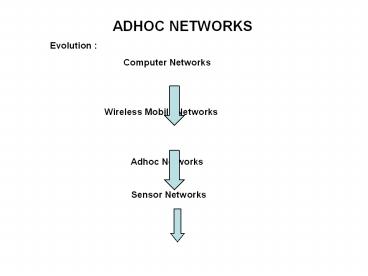
ADHOC NETWORKS Evolution Computer
Networks Wireless Mobile
Networks Adhoc Networks Sensor
Networks
2
Networks provide users access to information
communication Computer Networks Interconnected
collection of autonomous Computers 1. Wired
Network Physically connected through cables 2.
Wireless Mobile Networks Supported by a fixed
wired infrastructure
A single hop wireless radio communication to
access a base station that connects it to the
wired infrastructure 3. Adhoc Networks Does
not use any fixed infrastructure High
mobility. Therefore Mobile Adhoc Networks
(MANET)
3
Network Classification by Size
- Classification of interconnected processors by
scale.
4
Client-Server Model
- The client-server model involves requests and
replies.
5
Peer-to-Peer Applications
- In a peer-to-peer system there are no fixed
clients and servers.
6
Wireless LANs
- (a) Wireless networking with a base station.
(b) Ad hoc networking.
7
- What is an ad hoc network
- A collection of nodes that can communicate with
each other without the use of existing
infrastructure - Each node is a sender, a receiver, and a relay
- There are no special nodes
- No specialized routers
- Nodes can be static or mobile
- Can be thought of as peer-to-peer communication
8
- Ad hoc networks are wireless networks
- Decentralized networks, in which each node acts
as both an endpoint and a router for other nodes - increase the redundancy of the network and open
up the possibilities for network scaling as well - self-organizing networks which automatically
reconfigure without human intervention in the
event of degraded or broken communication links
between transceivers - Also called Self Healing Networks
9
- A node in an ad hoc network
- Two main components of a node
- From neighbors To neighbors
- Routing methods
- Each node maintains a table of routing
information. - Table entry destination X preferred neighbor.
- Data packet contains a destination ID in
header. - Packet received forward packet to the preferred
neighbor. Use table entry for the destination.
Local Task Routing
10
- Some features
- These networks may have bridges or gateways to
other networks such as wired Ethernet or 802.11 - the strength of their architecture is that they
do not require a base station or central point
of control. - Automated network analysis through link and route
discovery and evaluation are the distinguishing
features of self-healing network algorithms - Through discovery, networks establish one or more
routes between the originator and the recipient
of a message. - Through evaluation, networks detect route
failures, trigger renewed discovery, and in some
cases select the best route available for a
message.
11
- Mode of Operation
- Peer to peer multihop mobile wireless networks
- Information packets transmitted in a store and
forward manner from a source to an arbitrary
destination via intermediate nodes - Topology information noted in each node (Mobile
Host) - All MHs need not be in the range of each other
as MHs move topology changes. - Symmetric Asymmetric links
- If MH1 is within radio range of MH3, then MH3
is also within the Radio range of MH1
Communication links are symmetric or
bidirectional.
Asymmetric links are unidirectionaL
12
Mobile Adhoc Network (MANET) An autonomous system
of Mobile Hosts (MH also serving as routers)
connected by wireless links, forming a
communication network. Contrast In Cellular
networks, communication between two mobile nodes
completely rely on the wired backbone and the
fixed Base Stations In a MANET no such
infrastructure exists. Network topology may
dynamically change in an unpredictable manner
since the nodes are free to move
13
- Example Ad hoc network
- Nodes have power range
- Communication happens between nodes within range
14
What Is Different Here?
- Broadcasts of nodes can overlap -gt collision
- How do we handle this?
- A MAC layer protocol could be the answer
- If one node broadcasts, neighbors keep quiet
- Thus, nearby nodes compete for air time
- This is called contention
15
The Hidden Terminal Effect
- hidden terminals A, C cannot hear each other
- obstacles, signal attenuation
- collisions at B
- goal avoid collisions at B
- CSMA/CA CSMA with Collision Avoidance
16
(a)The hidden station problem. (b) The
exposed station problem.
17
- The Hidden Terminal Problem
- Wireless stations have transmission ranges and
not all stations are within radio range of each
other. - Simple CSMA will not work!
- C transmits to B.
- If A senses the channel, it will not hear Cs
transmission and falsely conclude that A can
begin a transmission to B. - The Exposed Station Problem
- This is the inverse problem.
- B wants to send to C and listens to the channel.
- When B hears As transmission, B falsely assumes
that it cannot send to C.
18
The 802.11 MAC protocol with CA
RTS
RTS
A
B
D
CTS
C
CTS
- Introduced to reduce collisions
- Sender sends Request To Send (RTS) ask
permission - Case A Receiver gives permission Clear To Send
(CTS) - Sender sends Data
- Receiver sends ACK, if received correctly
- Case B Receiver does not respond
- Sender waits, times out, exponential back-off,
and tries again
19
Why is this necessary?
- A sends RTS, and B replies with a CTS
- C hears RTS and avoids sending anything
- C could have been near B (not shown here)
- D hears CTS so it does not send anything to B
20
- ROUTING ISSUES IN ADHOC NETWORKS
- Nodes liable to move
- Highly dynamic network
- Rapid topological changes causing route failures
- Wireless channel acting as shared medium
- Available bandwidth per node is lower
- Nodes run on batteries which have limited energy
supply - Hence routing to be bandwidth efficient, having
low overheads, energy efficient
21
Proactive Routing Maintains routes between all
pairs of nodes regardless of whether all routes
are actually used. Two optimised variations of
these protocols are
(1) Distance Vector and (2) Link State In (1) a
node exchanges with its neighbours a vector
containing the current distance information to
all known destinations the distance information
propagates across the network and routes are
computed in a distributed manner at each node. In
(2) each node disseminates the status of each of
its outgoing links throughout the network in the
form of link state updates each node locally
computes routes using the complete topology
information
22
- On Demand (Reactive) Routing Find and maintain
only needed routes - Attractive when traffic is sporadic, bursty and
directed mostly towards a small subset of nodes. - Queuing delays occur at the source as routes are
created at session initiation when need arises - Dynamic Source routing Sender knows the complete
hop-by-hop route to the destination. These
routes are stored in a route cache The data
packet carries the source route in the packet
header. - Route Discovery By flooding the network with
Route Request (Query) packets. Each node
retransmits it unless it is the destination or it
has a route to the destination in its route
cache. Such a node replies to the request with a
route reply packet routed back to the original
source. The route of the reply packet is cached
at the source for future use.
23
- Hybrid Approaches Combination of Proactive and
Reactive - Augments a reactive protocol with some proactive
functionality - Each active destination periodically refresh
routes - Zone Routing Protocol is the example
- Defines zones for each node X which includes all
nodes that are within a certain distance in hops,
around the node X - A proactive link state protocol is used to keep
every node it reactively initiates a zone aware
of the complete topology within its zone - When X needs a route to Y not in its zone, it
reactively initiates a route discovery
24
- Common feature for the 3 routing schemes
- Nodes exchange routing messages and use this
information to guide future routing decisions. - An entirely different routing scheme is Location
based routing - Assumes each node knows its own location
- Nodes use GPS GLOBAL POSITIONING SYSTEM
- Every node learns location of its immediate
neighbours by exchanging hello messages - Location of potential destination nodes is
assumed to be available via this location service - Source sending a packet to destination uses ds
location to find a neighbour closest in
geographic distance to d forwards packet to
that neighbour. That neighbour repeats the
process until reaching d
25
Flooding Source Node simply broadcasts data to
neighboring nodes Each Node hearing the broadcast
for the first time rebroadcasts it Broadcast
propagates until every node has heard the packet
and transmitted it once Delivers data to every
node in the connected component of the
network Suitable when node mobility is high
otherwise inefficient A node may receive the same
packet from several neighbours Other flooding
techniques also available
26
- Wireless Routing Protocol (WRP)
- An important proactive routing approach
- Table driven protocol with the goal of
maintaining routing information among all nodes
in the network - Each node responsible for maintaining four tables
- Distance table
- Routing table
- Link-cost table
- Message Retransmission List (MRL) table
27
- Mode of Operation
- Peer to peer multihop mobile wireless networks
- Information packets transmitted in a store and
forward manner from a source to an arbitrary
destination via intermediate nodes - Topology information noted in each node (Mobile
Host) - All MHs need not be in the range of each other
as MHs move topology changes. - Symmetric Asymmetric links
- If MH1 is within radio range of MH3, then MH3
is also within the Radio range of MH1
Communication links are symmetric or
bidirectional.
Asymmetric links are unidirectionaL
28
- SOME ROUTING ATTACKS
- Wormhole attacks Two collaborating malicious
nodes create a tunnel to falsify the hop count
metric. - Rushing attack targets routing protocols that
choose routes on what message arrives first.
Malicious route message will be rushed to block
legitimate messages - Sybil attacks one malicious node takes up
multiple identities to project a false topology
29
- Sensor networks
- Low-bit-rate, low-grade data that is aggregated
and distilled into characterized by a large
quantity of nodes per network, where each node
produces useful information. - Some possible applications
- Traffic monitoring Control
- Sensors placed at strategic locations in road
junctions assess traffic intensity/congestion and
convey information to controlling officers so as
to select alternative route for incoming traffic - Goods management applications
- commercial goods equipped with inexpensive
wireless nodes that communicate information about
their state and place of origin.
30
WIRELESS SENSOR NETWORKS WSN is a special case of
Adhoc Networks with reduced or no
mobility Combine wireless communication minimal
computation facilities with sensing of physical
phenomenon which can be easily embedded in our
physical environment A sensor node consists of a
radio front end, a microcontroller, power supply
and the actual sensor all in a single device A
sensor consists of a transducer, an embedded
processor for local processing, small memory unit
for storage of data and a wireless transceiver to
transmit or receive data, all these run on the
power supplied by the attached battery Eg The
Mica Mote
31
Some advantages of WSN Ease of deployment can
be put anywhere, anytime. Extended range One
large wired-sensor can be replaced by many
smaller wireless sensors for the same cost Fault
tolerant if one macro-sensor fails, monitoring
of its area is gone. Failure of one node in WSN
does not affect operation Mobility ease of
redeployment Some Challenges Limited energy
supply, limited computing power, limited
bandwidth of the wireless connecting links Energy
management technique an important issue
32
Some numbers for 802.11
- Typical radius of power-range 250m
- Interference range 500m
- At 500m one can not hear, but they are bothered!
- RTS packet 40 bytes
- CTS and ACK 39 bytes
- MAC header is 47 bytes
33
- Some issues for investigative research
- Scalability
- Quality of Service
- Security
- Interoperation with the Internet
- Energy conservation
- Node cooperation
- etc
34
Performance Metrics(General Definitions)
- Utilization the percentage of time a device is
busy servicing a customer. - Throughput the number of jobs processed by the
system per unit time. - Response time the time required to receive a
response to a request (round-trip time). - Delay the time to traverse from one end to the
other in a system.
35
Network Performance Measures
- Latency usually implies the minimum possible
delay. Latency assumes no queuing and no
contention encountered along the path. - Goodput measured at the receiver rate in bits
per second of useful traffic received. Goodput
excludes duplicate packets and packets dropped
along the path. - Fairness either Jains fairness or max-min
fairness are used to measure fair treatment among
competing flows. - Quality of Service a QoS measure accounts for
importance of specific metric to one type of
application. e.g. jitter for streaming media
36
Network Performance Measures
- Channel utilization the average fraction of
time a channel is busy e.g. Util 0.8 - when overhead is taken into account (i.e.,
excluded from useful bits, channel utilization is
often referred to as channel efficiency - Throughput bits/sec. successfully transmitted
- e.g. Tput 10 Mbps
37
End-to-end packet delay
- End-to-end packet delay the time to deliver a
packet from source to destination. - most often we are interested in the packet delay
within the communications subnet - This delay is the sum of the delays on each
subnet link traversed by the packet. - Each link delay consists of four components
38
Packet Delay
- The processing delay PROC between the time the
packet is correctly received at the head node of
the incoming link and the time the packet is
assigned to an outgoing link queue for
transmission. - The queueing delay QD between the time the
packet is assigned to a queue for transmission
and the time it starts being transmitted. During
this time, the packet waits while other packets
in the transmission queue are transmitted. - The transmission delay TRANS between the times
that the first and last bits of the packet are
transmitted. - The propagation delay PROP between the time the
last bit is transmitted at the head node of the
link queue and the time the last bit is received
at the next router. This is proportional to the
physical distance between transmitter and
receiver.
39
End-to-End Packet DelayLink packet delay
PROC QD TRANS PROP.
- end-to-end packet delay sum of ALL link packet
delays. - Be Careful !! end-to-end can be defined
- either from Host-to-Host or only within the
sub-network.
40
THANK YOU
Recommended
CrystalGraphics Presentations


![[AD Hoc Networks] PowerPoint PPT Presentation](https://s3.amazonaws.com/images.powershow.com/8371435.th0.jpg?_=20161231113)


