
Fermilab - PowerPoint PPT Presentation
1 / 59
Title:
Fermilab
Description:
Place H atom in an electric field and strip away its electron ... the direction of its motion while the acceleration system restored momentum ... – PowerPoint PPT presentation
Number of Views:45
Avg rating:3.0/5.0
Title: Fermilab
1
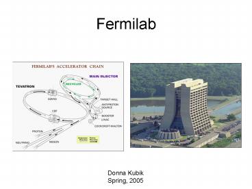
Fermilab
Donna Kubik Spring, 2005
2
Fermilab
- Special thanks to many at Fermilab for technical
guidance and friendship among the many are Todd
Johnson, Jim Morgan, Dave Capista, Linda
Spentzouris, Jean Slaughter
3
Main Control Room
4
Preaccelerator
5
Preaccelerator
- The Cockcroft-Walton is a classic multistage
diode/capacitor voltage multiplier
6
Production of H- ions
- Place H atom in an electric field and strip away
its electron - Protons will congregate on the Cs metal surface
- The metal has free electrons.
- Cs, with a very low work function, makes it easy
to attract electrons from the metal
7
Production of H- ions
- Every once in awhile, an incoming proton will
knock a proton with two electrons off the surface
of the Cs - The negative H- will move away from the negative
surface and get accelerated down the column to
750 keV
8
Preaccelerator
- Accelerates H- ions to 750 keV for injection into
the Linac - Like the Van de Graaff, the accelerator starts
out with negative ions, but for a different
reason - H- facilitates multi-turn injection into the
Booster - This will be described below in the section on
the Booster
9
Linac
10
Linac
- The Linac takes the 750 keV H- ions from the
Preacc, accelerates them to 400 MeV, and then
sends them on to the Booster. - There are five drift tube cavities and seven side
coupled cavities - The drift tube Linac makes up the first stage of
the Linac and the side-coupled Linac is the
second stage
11
Drift tube Linac
- Vacuum vessel for drift tube Linac
- Inside the vessels are drift tubes of increasing
length to accommodate increasing velocity of the
H- - There are quadrupoles inside the drift tubes to
focus the beam
12
Side-coupled Linac
- With side-coupled cavities, each individual cell
is a separate accelerating cavity coupled to
other cells in the module - The module is not one cavity with drift-tubes but
rather several separate cavities powered by the
same RF source by coupling.
13
Neutron Therapy
- Uses 66 MeV H- ions from the Linac to produce
neutrons for cancer therapy at the Neutron
Therapy facility (NTF) - First operational in 1975
- Similar to the Clinical Neutron Therapy System
(CNTS) at the University of Washington
14
Booster
15
Booster injection
- The revolution period in Booster at injection is
2.22 µsec, while the pulse length in Linac is
approximately 40 µs long - The 400 MeV chopper selects only a portion of the
Linac beam the remainder of the beam is sent to
one of the Linac dumps - Extending the chop width generates multiple
Booster turns - The Linac beam pulse is long enough to run about
18 turns (18 turns would be a 39.96 µs chop
length selected from the 40 µsec Linac pulse) - Operationally, the practical limit for maximum
intensity is 5 or 6 turns
16
The need to inject negative ions
- But how is more than 1 turn added to the Booster
without knocking out the protons that are already
circulating inside the Booster? - This is facilitated by injecting negative ions,
as described on the next slide.
17
Orbmp
18
Booster
- The booster is a rapid-cycling (15 Hz)
synchrotron - Shown are the combined function magnets and RF
cavities - Total of 17 RF cavities sprinkled around the
Booster
Combined function magnets
RF cavitites
19
FNALs Booster is very similar to CESRs
synchrotron
- Both synchrotrons use combined function magnets
and resonant circuits
CESRs synchrotron Built under the direction of
Robert Wilson First beam in late 1960s?
Fermilabs Booster synchrotron Built under the
direction of Robert Wilson First beam 1970?
20
Booster
- The Booster magnets are part of a 15 Hz resonant
circuit - Energy is exchanged between the magnets and the
capacitor banks with the power supply making up
the losses
Capacitor bank for magnet power- resonant circuit
Combined function Magnets - inductors
21
Booster
- A resonant power supply system uses a sinusoidal
current waveform to excite the magnets
Capacitor bank for magnet power- resonant circuit
Combined function Magnets - inductors
22
Acceleration
- RF energy, delivered by the 17 RF cavities,
accelerates the proton beam over the rising
portion of the sinusoidal magnet current
waveform. - Acceleration cycles occur at 15 Hz
23
Acceleration
- There is a DC offset to the AC magnet current, so
that the curcent is always positive. - It would be difficult to do multi-turn injection
right at the point where the energy is changing
the fastest. - With the offset, injection occurs on the
"flatter" part of the sinewave.
24
Main Injector
25
Main Injector/Recycler
- The main injector was built to replace the Main
Ring in the Tevatron tunnel - The Main Ring is seen above the Tevatron in the
photo. - The MR was not actually removed, it was abandoned
in place. - The main ring quads (red magnets), however, were
removed and reused
An old view of the Tevatron tunnel with Main
Ring magnets still present
26
Main Injector/Recycler
- Main Injector
- Accelerates protons
- Delivers protons for antiproton production
- Accelerates antiprotons from the Antiproton
Source - Antiproton Recycler (green ring)
- The Recycler doesn't actually recycle that plan
was given up. - Now it stores antiprotons from the Accumulator to
limit the peak stack size, which keeps the
production rate up.
27
Antiproton Source
28
Antiproton Source
- Three main components
- Target
- Debuncher
- Accumulator
29
Target
- A single batch of protons with an intensity of up
to 5 X 10¹² is accelerated to 120 GeV in the Main
Injector - The beams strikes the nickel production target in
the target vault and produces a shower of
secondary particles
30
Target
- The resulting cone of secondary particles is
focused and made parallel by means of a Lithium
lens - A pulsed dipole magnet bends all
negatively-charged particles of approximately 8
GeV into the AP2 line while most of the other
particles are absorbed within a beam dump - From the AP2 line, the anitprotons travel to the
debuncher and then to the accumulator
31
Two types of cooling
- Betatron (or transverse cooling) is applied to a
beam to reduce its transverse size, i.e. to
reduce its horizontal or vertical emittance
- Momentum cooling systems reduce the longitudinal
energy spread of a beam by accelerating or
decelerating particles in the beam distribution
towards a central momentum
32
Debuncher
- The momentum spread of the 8 GeV beam of
secondaries is reduced through bunch rotation and
adiabatic debunching. - Both betatron (transverse) stochastic cooling and
momentum (longitudinal) cooling is applied to
reduce the beam size and momentum spread
Debuncher (outer,light blue ring)
33
D to A
- Just before the next pulse arrives from the
target, the antiprotons are extracted from the
Debuncher and injected into the Accumulator via
the D to A line
D to A line
34
Accumulator
- Successive pulses of antiprotons are stacked into
the Accumulator 'core' by means of RF
deceleration and momentum stochastic cooling - The antiprotons in the core are maintained there
by momentum and betatron cooling systems
Accumulator (inner, dark blue ring)
35
Accumulator
- After several hours, enough antiprotons have been
accumulated to initiate a transfer to the Main
Injector and Tevatron for a store (or to the
Recycler via the Main Injector).
Accumulator (inner, dark blue ring)
36
Tevatron
37
Tevatron
- Receives 150 GeV protons and antiprotons
- Cryogenic magnets
- Normal-conducting (warm) RF cavities, all located
at FO (do not need to be evenly spaced around the
ring) - Accelerates to 980 GeV
- Stores beam providing pp-collisions for CDF and
DO
38
Tevatron map
39
Tevatron magnets
- All Tevatron magnets are superconducting
- 4.2 Tesla bend field (red magnets)
- Quadrupoles (yellow)
- Tevatron correction elements are superconducting
coils located within the main Tevatron quadrupole
cryostats
40
Tevatron FODO lattice
FODO lattice
41
Parasitic crossings
- The Tevatron operates with 3 trains, 12
bunches/train of each species - This would result in 70 parasitic crossings
- (36x2)-270
- Note the (-2) is because we want the beam to
cross at CDF and DO - So, like CESR, the Tevatron uses separators to
minimize the effect of the parasitic crossings
Tevatron separator
42
Parasitic crossings
- But unlike CESR, synchrotron radiation is minimal
in the Tevatron, so the electrode design did not
need to take that into consideration - The Tevatron separators consist of two parallel
plates, separated by 5 cm, with a potential
difference of 200kV DC between them - They can be constructed in either horizontal
and vertical configurations. The parts for each
type are identical
Tevatron separator
43
Helix
- In CESR, the electrons and positrons were
separated with a pretzel orbit in just one plane
(horizontal) - In the Tevatron, the protons and antiprotons are
separated via helical orbits - Horizontal and Vertical separators spaced roughly
90 degrees apart in phase generate the helix
(compare circular polarization)
Tevatron separator functions
44
Helix
- But there is no desire to separate protons and
antiprotons at CDF and DO!
Tevatron separator functions
45
Tevatron energy
- The energy is calculated from the magnetic field
in the dipoles and the revolution frequency. - The RF frequency is known with great precision,
probably better than anything else about the
machine. - The cross section predictions have bigger sources
of uncertainty than the energy
46
Operators job
- At first glance, it looks like a Day in the Life
of an operator is identical at each
accelerator
47
Operators job
- Fermilab
- Maintain luminosity
- Make sure machine is ready to refill
- CESR
- Maintain luminosity
- Make sure machine is ready to refill
48
Operators job
- But the properties of electrons vs. hadrons make
a Day in the Life of an operator very different
at each machine - The duration of a store (the time before the
storage ring must be refilled) differs
49
Store duration
- Fermilab
- Store duration 24 hours
- Luminosity lifetime
- 11-13 hours
- Filling time
- The Tevatron fill time is 30 minutes, but the
total turnaround time is 2 hrs with the
tune-ups, etc.
- CESR
- Store duration 1 hour
- Luminosity lifetime
- 2-3 hours
- Filling time
- 5 minutes
50
Store duration
- Fermilab
- CESR
1 day
1 day
51
CESR
52
Tevatron
53
Tevatron
Proton intensity Antiproton intensity
(different scale!) Luminosity
54
Why length of stores differ
- Fermilab
- Lower luminosity
- 50x1030 cm-2 s-1
- Higher energy
- 980 GeV
- CESR
- Higher luminosity
- 1280x1030 cm-2 s-1
- Lower energy
- 5 GeV
55
Why length of stores differ
- The combination of lower energy and higher
luminosity at CESR results in beams that are more
disrupted in the collisions, leading to a much
shorter lifetime - In addition, even without any collisions, the
lower-energy beams in CESR are more susceptible
than the Tevatron beams to other influences, such
as beam-gas scattering, which cause beam loss and
reduced lifetime - Even though the electron beams in CESR are
radiation-damped, the net effect is a poorer
lifetime for the CESR beams
56
Radiation damping
- Synchrotron radiation reduces the momentum of the
particle in the direction of its motion while the
acceleration system restored momentum parallel to
the central orbit
y
Energy loss from synch radiation
Energy restored from RF
x
57
What happens between stores
- Fermilab
- Maintain luminosity
- Attend to any tuning requests from the many
experiments (DO, CDF, MiniBooNE, MINOS, Meson
Test Beam Facility, etc. - Make sure the Preacc, Linac, Booster, and Main
Injector, Tevatron are ready for the next fill - Accumulate the antiprotons for the next fill
- Monitor cryogenics
- CESR
- Maintain luminosity
- Attend to any tuning requests from CLEO and CHESS
- Make sure the Linac is ready for the next fill
58
Operators
- Fermilab
- Need a crew of 4-5 operators
- CESR
- One operator
59
Smooth Operator SADE
Recommended
CrystalGraphics Presentations


