
Early Warnng Disaster Management - PowerPoint PPT Presentation
Title:
Early Warnng Disaster Management
Description:
Electronic Control and Netwroking – PowerPoint PPT presentation
Number of Views:136
Title: Early Warnng Disaster Management
1
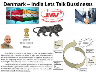
Denmark India Lets Talk Bussinesss
2
GOVERNMENT OF INDIA NODAL MINISTRIES /
DEPARTMENT FOR DISASTER MANAGEMENT
DISASTERS NODAL MINISTRIES Natural
Disasters Agriculture Air Accidents Civil
AviationCivil Strife Home AffairsRailway
Accidents RailwaysChemical Disasters Environmen
tBiological Disasters Health family
WelfareNuclear Accident Atomic Energy
3
National Response Mechanism
4
Disaster Management and Early
Warning Systems
June 2017
Safe Practice in Earthing and Protection Almost
30000 people die due to Nature Disaster . 20
of death occur due fires in Forest . 30
deaths that occur in Earth Quake 30 deaths due
to Lightning due to Rail 10 death due to
Floods 10 deat due to wind
5
Disaster MEAN(Emergency)
- Any incident which impact Mass Live comes under
disaster reason may be Weather - (Wind,Water,Cloud) and Earth Reaction.
- Another may Fire in Jungle.
- Prevention
- Managing Alert Messasge by Authorties.
- Early Warning Ligthning,Earthquakes,Sunami,High
Wind Speed - Countinous Collection of data from Warning
Devices and Analyse - Awarness and Education Programme
6
(No Transcript)
7
(No Transcript)
8
Early Warning Disasater Management
- System Concept Design often starts with a
detailed Site Survey during Disaster Requirements
and for the Warning System Solution for the said
area - Integration to other systems such as Fire
Gas, Public Address, PABX etc. Types of warning
required. Desired System Functionality
Inspection of Site Conditions such as Hazardous
Areas, Type of Dangers etc. Background Noise
Level, Noise Mapping and Acoustic Analysis. - Based on the outcome here of a Selection for
Product Range to offer in Effective planning and
designing best the Warning System Solution. - HSS Engineering has more than 40 years
experience in Public Address/General Alarm (PAGA)
and Mass Notification Systems that are used for
indoor and outdoor warning at Military,
Industrial, Petrochemical and Nuclear Facilities
as well as National Civil Defense Systems. - As one of the World Leaders in Mass Notification
Systems, we know that the origin of a good system
design comes from proper planning. The
interaction of hardware and software can be
complex and requires a good dialogue between the
customer and our engineers. In many cases, local
standards also affect the best solution for the
customers Warning System - India Denmark Commitment to Safe Guard Human
Life (Early Warning)
9
Early Warning System/Alert
10
Lightning Detection NetworksSensors detect the
radio waves emitted by lightning strokes
11
JMV Instalation
12
Protection from Lightning Charges
13
Picture Instalation ESE Type LA
14
- Technology for early detection of potential
earthquakes zone
15
Earth Quake Information
16
(No Transcript)
17
Deep Sea P Sensor
18
Suggested real-time sea level stations (India)
19
Surface Currents (India)
20
(No Transcript)
21
(No Transcript)
22
(No Transcript)
23
Disaster Information
24
Disaster Information
25
Earth Quake Early Warning
26
T Sunami Warning Systems
27
(No Transcript)
28
We always think about Safety of Each Life
29
Everybody Monitor for Human Safety
30
External/Internal Surge Source
31
Fire Accident in Solar PV Power PlantReason Lose
Contact Earthing Disorder and Lightning
32
Sikhana to Padega Hi Follow NBC2016
33
Earthing and Protection
34
Surge in Systems and Result
35
Surge in DC Application
36
(No Transcript)
37
LIGHTNING FORMATION
38
- Facts about Lightning
- A strike can average 100 million volts of
electricity - Current of up to 200,000 amperes
- Can generate 54,000 oF
- 10/350MicroSec/50KA Fault Current/Discharge in
Nano Sec - Protection
- Earthing Design100KA Fault Current/Joints
Exothermic /Flexible Down Conductor with
Shortest Route Less Corner
39
- Lightning Protection Standard use in India
- (IS2309 Now IEC 62305-5)NBC2016
- Working Principle Angullar No Compromise with
Design Max Protection 30Mtrs from One - No Product warrenty from Manufacturer
- High Maintenance Require
- Earthing below 10.00 Ohm
40
Lightning Risk assessment Study is actually the
measure of risk of a lightning strike and
probability of damages. As Per IEC62305-2.
- All these calculations are based on
- Lightning strike density inthat particular
area(provided byOMV i.e.Ng 8), - Danger for people,
- Occupation coefficient of structure,
- Relative location of site,
- Fire Risk,
- Associated services,
- Electrical Lines,
- Lightning Protection Level,
- Surge Arrestor and
- Dimensions of installation.
41
Lightning Safety Calculation
42
Lightning Risk Calcuator as per IEC6305
43
PASSIVE PROTECTION SYSTEM
44
The ESE air terminal is a
terminal which enables to generate artificially
an upward leader earlier than a simple rod, with
an ionization system, in order to establish a
special impact on its point. The capture of the
lightning strike being faster than a simple rod,
this technology enables to benefit from larger
protection areas, ensuring protection for large
dimensions structures. The generated protection
radius depends on the early streamer emission
value of the air terminal (?t in µs), its height,
and the efficiency of the protection. The
protection radius ensured by this type of air
terminal is 120 m (Protection level IV, height
60 m , early streamer emission time 60µs) The NFC
17-102 standard describes the installation
procedure for this type of air terminal. The
installation of this type of air terminal is easy
and cheaper than other technologies. It can
protect whole buildings with one E.S.E. air
terminal. It enables the protection of a
structure and its environment, the protection of
opened areas and well integrate in the
architecture of a structure without aesthetic
alteration. 1 ESE, 2 down conductors and 2
earthing systems are necessary to ensure the
protection below
45
ESE Installation Guidence
ESE AT with radius protection form 32 mtr to 107
mtr.
DMC Insulator .
GI/FRP Mast .
Down Conductor Copper / Copper Cadmium Cable 70
sq. mm
Copper Bonded Ground Earthing
46
Thimble
Joint all phase wire/ cable with the help of
crimping tools and lugs
Step 1
Separation Sheet
Fixed the separation sheet between all wires/
cables
Gel / Silicon
Step 2
Close the filled Silicon enclosure from top and
bottom , complete installation is done.
Step 3
47
(No Transcript)
48
Copper Clad Steel Solid ROD and Conductor
49
(No Transcript)
50
(No Transcript)
51
(No Transcript)
52
(No Transcript)
53
Copper Cladded Conductor For Electrical
Installation
The Copper Clad Steel Grounding Conductor is made
up of steel with the coating of 99.99 pure
copper. These conductors/ wires or strands are
equipped with the strength of steel with the
conductivity and copper with the better corrosion
resistance property. The concentric copper
cladding is metallurgic ally bonded to a steel
core through a continuous, solid cladding
process using pressure rolling for primary
bonding. The copper cladding thickness remains
constant surrounding steel. We use different
steel grades for the steel core result in Dead
Soft Annealed, High strength and Extra High
Strength Characteristics. The Copper Clad Steel
Wire yields a composite conductivity of 21, 30
and 40 IACS, and available in Annealed and Hard
drawn. We are delivering products with varied
conductivity and tensile strength as per the
customer need. Further, the wire can be processed
to be silver plated or tinned copper clad steel
wire.
54
Most Efficient JointProcess
It is efficient and superior to all existing
surface to-surface mechanical retention
connectors.
55
What is Exothermic Welding System?Copper to
Bi-Metal and Alumenium
- Types of Exothermic Joints
- Possible to join any bi metal except aluminum
- Exothermic welding is a process of making
maintain free highly molecular bonding process is
superior in performance connection to any known
mechanical or compression-type surface-to-surface
contact connector. Exothermic weld connections
provide current carrying (fusing) capacity equal
to that of the conductor and will not deteriorate
with age. - It offers Electrical connections between two or
more copper to copper and copper to steel
conductors. - Highly portable method as it does not require
any external power source or heat source, so it
can be done almost anywhere. - It provides strong permanent molecular bond
among metallic conductors that cannot loosen and
further will not deteriorate with age. - Connection does not corrode with time and it
offers permanent conductivity.
56
Installation
ESE AT with radius protection form 32 mtr to 107
mtr.
DMC Insulator .
GI/FRP Mast .
Down Conductor Copper / Copper Cadmium Cable 70
sq. mm
Copper Bonded Ground Earthing
57
(No Transcript)
58
(No Transcript)
59
(No Transcript)
60
(No Transcript)
61
JMVs Clients
62
Contact Professionals for Advise
63
We Protect You Use Electrical SafetyEarthing
Protection
64
Contact our Team JMV INDIALeader and
Insperation behind Mr.Neeraj Saini
neeraj_at_jmv.co.inMr.Mahesh Chandra Manav Brand
JMV HOD manav_at_jmv.co.inwww.jmv.co.inMoblie
-919910398999Telecom -9191204590000
Recommended
CrystalGraphics Presentations


