
Operator manual for fadal pendant - PowerPoint PPT Presentation
Title:
Operator manual for fadal pendant
Description:
A carelessly or improperly operated VMC can cause serious injury or death as well as damage or destruction of equipment. The emergency and safety procedures in this manual are to help users operate the VMC in a safe manner. Fadal has no control over the applications the operator may use the VMC for and is not responsible for injuries or equipment damage. Download operator manual for fadal pendant from itscnc.com. With our documentation we also include preventative maintenance tips to help avoid future failures. Read and understand the Operator’s Manual. – PowerPoint PPT presentation
Number of Views:40
Title: Operator manual for fadal pendant
1
Fadal
Operator Manual
Section 2 Pendant
Video ON/OFF Switch
When the machine is idle for long periods of
time, the video screen should be turned off.
This is necessary when the machine is left on
overnight. If the machine is left on overnight,
press the EMERGENCY STOP button before leaving
the machine.
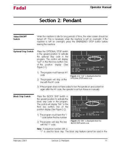
Optional Stop Switch
Place the OPTIONAL STOP switch in the upward
position to activate the optional stop code in
the program. The control will display opt in
the third box bottom line
of the position display (See Figure 2-1).
- The program must have an M1 code.
- The program will stop on the line with the M1
code.
Figure 2-1 Opt is displayed when the OPTIONAL
STOP switch is on.
3) If the program does not have codes to turn the
spindle on and coolant on again after the M1
code, the operator must turn these on manually.
Block Skip Switch
Place the BLOCK SKIP switch in the upward
position to activate the block skip code in the
program. The control will display blk in the
third box bottom line of the position display
(See Figure 2-2).
1) The program must have the / code before
the line number.
Figure 2-2 Blk is displayed when the BLOCK
SKIP switch is on.
2) The program will skip the line with the /
code.
Note A sequence number with a / is used for
block skip. The block skip feature cannot be used
in the
February 2001
Section 2 Pendant
11
2
Fadal
Operator Manual
middle of the line. It must appear before the
sequence number.
EXAMPLE
N4 Z.25 F20.
- /N5 L101 With the block skip on, the program
will skip line five. - N6 X2.4 With the block skip on, this line will
be machined after line N4 To add a / to a
sequence number - From the page mode (PA) or edit mode, move the
cursor to the line you want to edit. - Press the C key to change the line.
- Press the / key.
- Press the ENTER key two times.
Keylock
The key lock on the pendant is used to protect
the program from unauthorized editing. When any
of the commands that can alter the program are
used, the message command prohibited by key
lock appears. This feature also prohibits the
PU command.
To prohibit program editing
- Put the key into the key slot on the pendant (See
Figure 2-3). - Turn the key so the slot is in the horizontal
position. - Remove the key and store it in a secured area.
Figure 2-3 KEY LOCK used to protect
unauthorized editing of programs.
- To allow program editing
- Put the key into the key slot on the pendant.
- Turn the key so the slot is in the vertical
position. - Note See also NOEDIT feature.
12
Section 2 Pendant
February 2001
3
Fadal
Operator Manual
Alternate NOEDIT Feature
The NOEDIT feature is used to prohibit the
operator from editing or punching (downloading)
the program in memory. The only thing allowed is
to delete the program from memory. Any editing
should be accomplished in an editor outside the
machine and then resend the program to the
machine.
1) On the line with the O word type a comment
with the word NOEDIT within the first sixteen
characters.
EXAMPLE
N1 O6 (NOEDIT FACE PLATE
Positioning Read Out Display
Figure 2-4 shows the sections and the purpose of
each section used in the positioning read-out
display. a Position readout. b Axis load or
following error. c Distance to go. d
Programmed RPM (S9000). e Programmed Turret
location (T1). f Actual RPM. g Programmed
feedrate (F100). h Active G codes. i
Active tool offsets. j Last executed M code.
k Actual feedrate (95). l Optional stop on
(OPT). m Running buffer. n Current program.
o Current fixture offsets (E1). p Block skip
on (BLK). q Tool load compensation.
BLK OPT
Figure 2-4 The upper portion of the monitor
screen showing the positioning read-out display.
February 2001
Section 2 Pendant
13
4
Fadal
Operator Manual
How to Display the Position Read-out
1) Press the JOG button to see the positioning
read-out.
- From the command mode, type MD then press the
ENTER button or press the MANUAL button to see
the positioning read-out. - Press the AUTO button to see the positioning
read-out. - The position read-out is showing the position of
the tool in relation to the position set to zero
by the SET (axis), SETH commands (or in relation
to the cold start position before the SET
(parameter) commands are used). - If a program contains the code G92, all positions
are relative to the position preset by the G92
code. - When fixture offsets are used, the read-out is
relative to the active fixture offset home
position. - Note When jogging in the metric mode .01
in..254 mm, .001 in..0254 mm, - .0001 in..00254 mm. The minimal move in the
metric mode is .00254 mm (even though the
positioning read-out displays three places after
the decimal).
Axis Load Display
The axis load amperage can be displayed for the
AC Brushless axis systems. The axis load can be
displayed directly to the right of each axis
position displayed at the top of the screen. The
default setting is axis following error.
- To select load percentage, the operator must type
SETP from the command mode. - Press the space bar two times to get to the last
page of the machine parameter pages. Press the
ENTER, D, or U key to move the cursor to the
axis display selection. - Select load percentage so that the machine will
display axis load. Then press the MANUAL key to
exit the parameters page.
14
Section 2 Pendant
February 2001
5
Fadal
Operator Manual
Manual Data Input Display
The MDI screen will display the modal codes in
effect and the distance to go. This screen is
similar to the positioning read-out screen in
Auto (See Figure 2-5).
Figure 2-5 Manual Data Input.
Large Format Display
Depressing the key during Auto will enable the
large format screen (See Figure 2-6). To return
to the normal screen press the key again.
Note On the 32MP controller, hold down SHIFT
key and press the key. Figure 2-6 Large Format
Display.
Modes
1) The control works in different modes of
operation. Each mode of operation has a specific
job to perform.
EXAMPLE
The list mode is used only for listing the
program to the screen. The jog mode is used only
for jogging the tool.
- The command mode is the upper most mode and it
acts like a dispatch center for all the other
modes. - From the command mode the operator can go into
the menu mode to look at the menu. - To go to another mode of operation, the operator
must first go back to the command mode, before
going to another mode. - The primary function of the MANUAL key is to get
out of any mode of operation and get back to the
command mode.
February 2001
Section 2 Pendant
15
6
Fadal
Operator Manual
4) Two letter commands are used to get into other
modes, and the MANUAL key is used to get back to
the command mode. Note The MANUAL key is also
used to enter the MDI mode.
Quick Keys Menu
There are three separate prompting menus within
the machine control. They are the Quick Keys
Menu, the Edit Menu, and the Functions Menu.
These menus prompt the operator for input to
perform machine commands. The Quick Keys menu is
used for quick setup functions. Program editing
is accomplished with the Edit Menu. The
Functions Menu is utilized to perform machine
tasks. These menus are activated or deactivated
within the machine parameters. Use the SETP
command, and the CMD MENU parameter, to turn the
menus on or off. When the menus are off, the
machine is operated by commands (See the Command
Mode explanation on the following page). The
Quick Keys Menu is selected by pressing the space
bar from ENTER NEXT COMMAND.
Edit Menu
The Edit Menu is selected by pressing the space
bar twice ENTER NEXT COMMAND, and allows editing
or viewing the currently active program. This
menu functions the same as the PA command editor
(see PA Command).
Functions Menu
The Functions Menu is selected by pressing the
space bar three times from ENTER NEXT COMMAND.
The first twelve (12) lines display the currently
active program. The bottom four (4) lines
display the Functions Menu options.
These menu options are selected by number input.
The operator may switch between the Function
Menu, the Quick Keys Menu and the Edit Menu by
pressing the SPACE bar. Selection of menu
options may display additional menu options. The
top line of the subsequent menus displays the
previous menus selected. Press the MANUAL key at
any time to abort the process and return to the
main menu. The Users Manual has a detailed
explanation of each function associated with
these menus.
Using the Command Mode
To enter a command, the control must be in the
command mode. The command mode is recognized by
the words at the bottom of the screen, enter
next command. A list of accepted commands can be
found in the Users Manual, chapter 8, or the
Command Summary section of this chapter. The
menu in the control also has a list of accepted
commands. (See Menu Mode)
16
Section 2 Pendant
February 2001
7
Fadal
Operator Manual
- The primary use of the MANUAL key is to get into
the command mode. Below are examples of how the
MANUAL key is used to access the command mode
from various modes. - To go from the manual data input (MDI) mode to
the command mode, at any time press the MANUAL
key. - To go from the jog mode to the command mode,
press the MANUAL key at any time. - To get into the command mode when waiting-,
single step-, or slide hold- are flashing on
the screen, press the MANUAL key. - To go from the auto mode to the command mode
press the SLIDE HOLD key or the SINGLE STEP key,
then press the MANUAL key. - To get into the command mode from the list mode,
the change mode, the sum mode, the insert mode,
the learn mode, the tool changer mode, or the PR
procedure press the MANUAL key at any time.
Cursor in the Command Mode
The cursor is the flashing lt symbol. When a key
is pressed and this symbol is present, the
letter, number, or symbol the key represents will
be printed on the screen.
The only place on the screen the cursor will be
found is in the lower left hand corner. 1) When
a key is pressed the cursor moves to the right.
EXAMPLE
ENTER NEXT COMMAND lt
ENTER NEXT COMMAND A lt Press the letter A and the
cursor will move to the right. ENTER NEXT
COMMAND ABC lt Press the letter B and C the
cursor will move to the right again. 2) The
BACKSPACE key will move the cursor to the left,
over the existing characters in the line.
EXAMPLE
ENTER NEXT COMMAND AB lt From the Example above
press the BACK SPACE once.
ENTER NEXT COMMAND A ltC Press it again and the
cursor will move to the left again. Notice the
letter C is showing.
February 2001
Section 2 Pendant
17
8
Fadal
Operator Manual
Note The control will only recognize characters
to the left of the cursor, when the ENTER button
is pressed. From the Example above, only the
letter A would be recognized if the ENTER button
is pressed. ENTER NEXT COMMAND AUlt Press the
letter U, it will be in the place of the letter
B and the cursor will now cover the letter
C. ENTER NEXT COMMAND AU,50lt,,1 If the ENTER
button is pressed now, only AU,50 will be
recognized. Note The control will not analyze
what is typed until the ENTER button is pressed.
Always look to see what is on the screen before
pressing the ENTER key. (See DELETE KEY for more
information on cursor movement).
Using the Delete Key
The DEL key can be used in the command mode,
change mode, insert mode, and manual data mode
to delete all characters to the left of the
cursor. Pressing the DEL key will not exit the
current mode, but will allow the operator to
retype the entire line.
EXAMPLE
ENTER NEXT COMMAND INlt (press ENTER)
IN N1 GOG9OS10000M3X1.56Y-3.976E1_at_ The delete
key was pressed here because it was noticed that
the letter O was used for the number 0 in G0 and
G90. Notice the _at_ symbol where the DELETE key
was pressed. The cursor has moved to the space
below the N1 line. The control is still waiting
for input on line N1. The control will only
recognize characters to the right of the _at_ symbol
and to the left of the cursor. N1
GOG9OS1000M3X1.56Y-3.976E1_at_ G0G90S10000M3X1.56Y-3.
976E1lt (press ENTER) N2lt Type the line
correctly and press the ENTER button, the control
will remain in the current mode.
18
Section 2 Pendant
February 2001
9
Fadal
Operator Manual
The insert mode was used as an Example above,
however, the DELETE button works the same way in
the modes mentioned above, and it can be pressed
as often as required. The DEL key may also be
used to delete a line of code from the program
while in the PA mode. (See PAGE, USING THE PA
COMMAND).
Using the Menu Mode
The menu mode is a list of accepted commands and
their proper usage format. It is a summary form
of the command section in the Users Manual. The
menu mode is only for help when using the
commands, it is not necessary to use the menu
mode to use the commands.
- From the command mode, type MU and then press the
ENTER key to access the menu mode. - The first page of the menu is the directory
(table of contents). This page has a list of all
the commands, and the page number containing the
explanations.
3) To get from page to page in the menu, three
methods can be used. Press the ENTER key to page
forward one page at a time. The listing will page
forward each time the key is pressed.
Method 1
Method 2
Press the BACKSPACE key to page backwards one
page at a time. The listing will page backward
each time the key is pressed.
Method 3
Type the page number of the page to jump to and
press the ENTER key. The menu will go directly
to the page number typed. This can be done at any
time, when in the menu mode. Type the number one
from any page of the menu, press the ENTER key,
and the menu will jump to the directory page.
Note To use a command, press the MANUAL key to
exit the menu mode. The page being viewed in the
menu mode will remain on the screen after exiting
to the command mode.
February 2001
Section 2 Pendant
19
10
Fadal
Operator Manual
This page intentionally left blank.
20
Section 2 Pendant
February 2001