
Diapositive 1 - PowerPoint PPT Presentation
1 / 25
Title: Diapositive 1
1
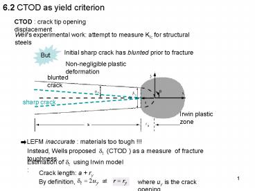
6.2 CTOD as yield criterion
CTOD crack tip opening displacement
Wells experimental work attempt to measure KIc
for structural steels
Initial sharp crack has blunted prior to fracture
Non-negligible plastic deformation
blunted crack
Irwin plastic zone
Instead, Wells proposed dt (CTOD ) as a measure
of fracture toughness.
Estimation of dt using Irwin model
Crack length a ry
where uy is the crack opening
2
Crack opening uy
(see eqs 4.40)
and also,
CTOD related uniquely to KI and G.
CTOD appropriate characterizing
crack-tip-parameter when LEFM no longer valid.
Can be proved by a unique relationship between
CTOD and the J integral.
3
6.3 The J contour integral as yield criterion
- More general criterion than K (valid for LEFM)
- Derive a criterion for elastic-plastic
materials, with typical stress-strain behavior
A?B linear
B?C non-linear curve
C?D non-linear, same slope as A-B
non-reversibility A-B-C ? C-D-A
Non unique solutions for stresses
elastic-plastic law replaced by the non-linear
elastic law
reversibility A-B-C C-D-A
Deformation theory of Plasticity
4
Definition of the J-integral
- Historically,
Rice defined a path-independent contour integral
J for the analysis of crack
showed that its value energy release rate in a
nonlinear elastic body with a crack
- J generalizes the concept of G to non-linear
materials
- For linear materials J G
- Load-displacement diagram potential energy P
P0
U Elastic strain energy
U
? (in general)
U
U Complementary energy
D
D0
D
Fixed-grips conditions
Dead-load conditions
5
- Definition of J using the potential energy P
A a B for a cracked plate with through crack
- Geometrical interpretation
and OB
OAB OAB
dU is the difference between the areas under OB
PdD appears as the area AABB
AABB
OAB
OBB
OAB
6
- In particular ,
dD
D
D0
At constant displacement
At constant force (dual form)
Generalization of eqs 3.38a and 3.43a to
non-linear elastic materials
Useful expressions for the experimental
determination of J
7
- Experimental determination of the J-integral
- Multiple-specimen method (Begley and Landes
(1972))
Procedure
(1) Consider cracked specimens with different
crack lengths ai
(2) For each specimen, record of the
load-displacement P-u curve under fixed-grips
8
(3) Calculation of the potential energy P for
given values of displacement u
area under the load-displacement curve
(4) Negative slopes of the P a curves
determined and plotted versus displacement for
different crack lengths
Critical value JIc of J at the onset of crack
extension (material constant)
9
- Single-specimen method by Rice , Merkle and
Corten
J can be determined directly from the
load-displacement curve of a single cracked
specimen.
Generally, when crack lengths that are important
compared with the unbroken ligament dimension.
Estimation formula derived by Rice et al. (1973)
for specimens in tension and under bending
The case of combined tension and bending treated
by Merkle and Corten (1974), modified by Clarke
and Landes (1979)
Principle
Writing of a relationship between load,
displacement and bodys characteristic lengths
using a dimensional analysis.
See for example pp 116-119 of Andersons book,
third ed.
Example
for the deeply cracked three-point bending or
compact tension specimen J is given by,
b ligament length
(application pb3 series7)
10
- J as a path-independent line integral
T traction vector at a point M on the bounding
surface G , i.e.
u displacement vector at the same point M.
n unit outward normal.
The contour G is followed in the
counter-clockwise direction.
11
Equivalence of the two definitions
Y
- 2D solid of unit thickness of area S ,
with a linear crack of length a along OX (fixed)
y
- Crack faces are traction-free.
O
X
x
- Total contour of the solid G0 including the
crack tip
a
Imposed tractions on the part of the contour Gt
Displacements applied on Gu
Proof
Recall for the potential energy (per unit
thickness),
The tractions and displacements imposed on Gt and
Gu are independent of a
Change of P due to a virtual crack extension
12
Considering the moving coordinate system x , y
(attached to the crack tip),
Thus,
However,
since
13
Thus,
We have,
The derivative of J reduces to,
14
Using the Green Theorem, i.e.
J derives from a potential
End of the proof
15
Properties of the J-integral
1) J is zero for any closed contour containing no
crack tip.
Closed contour around A
A
G
Consider
Using the Green Theorem, i.e.
We have
From the divergence theorem,
16
The integral becomes,
However,
since
Invoking the equilibrium equation,
0
Replacing in the integral,
17
2) J is path-independent
G3
G4
Consider the closed contour
We have
and
dy 0 along these contours
18
G3
G4
Note that,
G2 followed in the counter-clockwise direction.
and
Any arbitrary (counterclockwise) path around a
crack gives the same value of J
J is path-independent
19
J can be evaluated when the path is a circle of
radius r around the crack tip
G
r
crack
G is followed from q -p to q p
We have,
J integral becomes,
When r ? 0 only the singular terms remain
For LEFM , we can obtain
(if mode I loading)
(see eq. 6.58)
20
6.4 HRR theory
Hutchinson Rice and Rosengren
J characterizes the crack-tip field in a
non-linear elastic material.
- For uniaxial deformation
Ramberg-Osgood equation
a dimensionless constant
material properties
n strain-hardening exponent
Power law relationship assumed between plastic
strain and stress.
For a linear elastic material n 1.
21
- Asymptotic field derived by Hutchinson Rice and
Rosengren
Ai are regular functions that depend on q and
the previous parameters.
The product
varies as 1/r
Path independence of J
J defines the amplitude of the HRR field as K
does in the linear case.
22
Two singular zones can be identified
K
J
Small region where crack blunting occurs.
Large deformation
HRR based upon small displacements non applicable.
23
- Relationship between J and CTOD
Consider again the strip-yield problem,
y
dt
x
a
c
(slender zone)
The first term in the J integral vanishes because
dy 0
but
(see pb1 Series 8)
24
General unique relationship between J and CTOD
m dimensionless parameter depending on the
stress state and materials properties
- The strip-yield model predicts that m1
(non-hardening material, plane stress condition)
- This relation is more generally derived for
hardening materials (n gt1) using the HRR
displacements near the crack tip, i.e.
Shih proposed this definition for dt
m becomes a (complicated) function of n
The proposed definition of dt agrees with the
one of the Irwin model
Moreover,
in this case
25
6.5 Applications the J-integral
- J integral along a specific contour
- Example 6.5.2
- Example 6.5.3