
Discovery 1-4 Loop Analogue Addressable Control Panels - PowerPoint PPT Presentation
1 / 25
Title:
Discovery 1-4 Loop Analogue Addressable Control Panels
Description:
Discovery 1-4 Loop Analogue Addressable Control Panels. From 1-4 loops ... Automatic recognition of Apollo and Control Equipment outstations ... – PowerPoint PPT presentation
Number of Views:202
Avg rating:3.0/5.0
Title: Discovery 1-4 Loop Analogue Addressable Control Panels
1
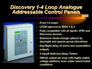
Discovery 1-4 Loop Analogue Addressable Control
Panels
- From 1-4 loops
- LPCB approval to EN54 2 4
- Fully compatible with all Apollo XP95 and
Discovery devices - Extensive mode-change options by day/night and
special group allocations - Day/Night delay of alarm and cause/effect outputs
- 4 Inbuilt Software Delay Timers
- 500mA output per loop with highly stable voltage
platform, even under mains-failed conditions
2
Discovery 1-4 Loop Analogue Addressable Control
Panels
- Additional Discovery detector functions
- Print Drift Compensation level by loop
- Print Device Date of Manufacture
- Enable/Disable LED pulsing mode
- Automatic recognition of Apollo and Control
Equipment outstations - User friendly controls and a clear, unambiguous
screen - Fully networkable with other Discovery and
Voyager panels - Complies with EMC and LVD Directives
- Windows-based, full upload/download PC software
package
3
Discovery 1-4 Loop Analogue Addressable Control
Panels
- New Phase 5 Software upgrade
- 61 customer Led Enhancements Including-
- Fast loop output response (3 seconds with BGU
operation - Latest Apollo devices supported including
intelligent reflective beam, discovery CO
detector, XP95 multisensor etc - Local cause / effect enhanced to 3 x capacity
- General output disablement facility
- Configurable class change pulse / continuous
- Full loop sounder synchronisation supported
4
Discovery Panel Hardware
Up to 14 fully functional repeater panels may be
connected via RS485 cable.
Up to 31 8-way panel enhancement boards may be
added. Two types are available 1)
fully-programmable inputs and relay outputs 2)
fully-programmable inputs and alarm outputs
Fully programmable network comprising other
Discovery and Voyager panels, graphics systems
and network repeaters.
Individual panels and Integra networks are
programmable via Windows PC package.
5
Mechanical Assembly
Motherboard and power supply located on a
removable chassis to assist cabinet installation.
Motherboard holds up to 4 loop cards
Display assembly located on the removable door.
LPC approved high specification switch mode power
supply.
Zonal LEDs and optional printer are located on
the display board.
Space for internal 12Ah battery set.
6
Cabinet Options
Surface Cabinets Cabinet colour reference is
RAL 7035 textured (Light Grey) All cabinets
are manufactured from sheet steel and finished in
satin texture epoxy powder stove paint.
Semi-Flush Cabinets The semi-flush bezel
locates to the rear of the bevelled edge of the
back box, leaving the bevelled edge and door
raised out from the wall. It is finished in the
same colour as the back box and is fitted by
means of pinch bolts, thus avoiding the need to
drill the cabinet. Fully Flush Cabinet
(Illustrated) Custom-made to a high quality,
full-flush bezels are available in brass,
stainless steel, or painted. This option is
achieved by fixing a flat bezel assembly to the
standard back box, replacing the standard door.
The panel comes with assembly already fitted but
may be supplied for later on-site fitting (this
may be a little time-consuming).
For details of panel dimensions see Application
Guide.
7
User Controls
The backlit LCD display gives information of
loop, device and zone number, device type and
event condition, together with a user-definable
text description.
The text descriptions give the user clear,
easy-to use functional controls.
The engineer accesses panel configuration
functions using the numerical designations. The
menu structure on the LCD display guides the
engineer through the different set-up facilities.
System LED indications are provided in addition
to the LCD display.
8
LCD Display
The device types which may be indicated are as
follows SOU - Loop sounder/sounder circuit
controller O/S - Input/Output device ION -
Ionisation smoke sensor MON - Monitor (zone
monitor, control monitor) OPT - Optical smoke
sensor HEAT - Heat sensor BGU - Call point or
call point monitor
9
Zone Indications
The Discovery panel is available with or without
the slide in zone indication chart
System LED indications are provided in addition
to the LCD display.
The printer slot and printer location studs are
available for easy printer fitting
10
Printer
This good quality printer uses a reliable Epson
mechanism.
Hinged access to allow easy ribbon change.
Engineers printer test button.
Open access to feed paper through mechanism.
Designed for easy replacement of the paper roll
onto the carrier.
This button advances the paper.
11
A1535 8 Way Relay Board
RS485 comms from panel motherboard.
Engineers DIL switches to set board address,
enable O/C or S/C inputs and disable
inputs/outputs.
8 inputs may be normally open or normally closed
and will register as fire or non-fire on the
panel as configured. Inputs are fully
programmable via the panel or PC cause/effect.
8 x 1Amp changeover relay outputs may be fully
programmed via the panel or PC cause/effect
programme.
Engineers links to disable functions for set-up
or maintenance purposes.
24V DC power.
12
A1536 8 Way Alarm Board
Engineers DIL switches to set board address,
disable inputs and outputs, test LEDs and test
alarms.
Engineers DIL switches to isolate alarm outputs
individually.
RS485 comms from panel motherboard.
8 x 1Amp two-stage alarm outputs may be fully
programmed via the panel or PC cause/effect.
8 normally open inputs which will register as
fire or non-fire on the panel as configured.
Inputs are fully programmable via panel or PC
cause/effect.
Alarm Fault LEDs.
Test alarms when switched to 0V.
Engineers buzzer disable link for set-up or
maintenance purposes.
24V DC power.
13
Extensive Users Menu
- User Functions
- Time/Date
- Delay
- Delay Enable/Disable
- Day/Night Modes
- Enable Day/Night/Auto/Off
- Enable/Disable
- Devices
- Zones
- Printer
- Sounders
- View
- View Event Log
- View Suppressed Events
- Test
- Point Walk Test
- Alarm Walk Test
- Clear Print Queue
User functions to disable individual loop
devices, a range of devices, full zones, the
printer and sounders.
User function to read the output delay and to
enable or disable its operation.
User function to select the DAY mode, NIGHT mode,
AUTO mode via timer, or OFF (XP95 default
settings).
User function to operate one man device test and
alarm audibility test.
14
Overview of the Engineers Menu
1. PANEL SETUP 1. LOOP SETUP 1. Loop
Configuration 1. Loop Contents 1. View Loop
Contents 2. Print Loop Contents 1. Reconfigure
Loop 2. Device Sensitivity (XP95/Discovery) 1.
Fire 2. Alert 3. Discovery 1. Print Drift 2.
Print Date 3. LED 4. Rapid Compensation 2. Zone
Allocation 1. Edit Device Zones 2. Print Device
Zones 3. View Device Zones
3. Loop Cause Effect 1. Device Group
Allocation 1. Edit Device Groups 2. Print Device
Groups 3. View Device Groups 2. Loop Output
C/E 3. Print Loop O/P C/E 2. I/O SETUP 1. Remote
Evacuate Mode 2. TEXT EDIT 1. EDIT COMPANY
NAME 2. EDIT Device TEXT
15
Windows-based PC Programming
Windows-based PC programming package for panel
set up, zones, text, local and network
cause/effect, Discovery mode types, sensitivity
levels and day/night timings.
16
Discovery Mode-change Maps
- The discovery panel provides the engineer with
the facility to set a mode sensitivity map for - Day use - for example, less sensitive in some
process areas during working hours - Night use - for example, maximum sensitivity
throughout entire building when not in use - Default - ignore day/night sensitivity maps, set
to XP95 equivalent - The engineer may set up each device into a day
map, and night map, and set the clock (week day
or weekend options) to switch between them
17
Discovery Mode-change Maps
- The end user may easily select between
- Day mode - manually holds all devices in the Day
mode setting - Night Mode - Manually holds all devices in Night
mode setting - Automatic - Day/Night mode determined by clock
- Off - To manually set all devices to default
(XP95 equivalent)
18
Discovery Temporary Mode Changes
- Loop outstation inputs may be configured to
change Discovery Multi-sensor modes. - Applications -
- Loading Bays - As a lorry enters, smoke detection
may be temporarily disabled - Theatre Stages - Stage hand may operate key
switch to de-activate smoke detection at
performance times - Hotel Function Rooms - Keyswitch at room entrance
to disable smoke detection during special events - Smoke Cloak Security - Multisensor smoke elements
may be disabled when the
smoke cloak is activated
19
Networking
- All talk - selective listen
- No Master panel or P.C. required and thus no
single Device of failure - Up to 15 active panels or 60 loops may be
networked together plus an
additional 17 passive nodes - Discovery panels, Voyager panels, network
repeaters and Alarm Manager
graphics systems - Conventional panels, extinguishant panels and
other equipment via network repeater and/or loop
I/O - Full event and cause/effect programming
across network - RS485 data communications
- Network repeater with up to 248 programmable
inputs and 248 programmable
outputs
20
Typical Network Illustration
RS485 comms to panel repeaters and expansion
cards.
Discovery, and Voyager panels may be networked
together with Network Repeaters, Alarm Managers
(Graphics) PCs.
Network repeater with up to 248 programmable
inputs and 248 programmable outputs.
RS485 network comms.
Engineers programming via PC.
21
Network Repeater
Up to 31 8-way panel enhancement boards may be
added to the Integra Network Repeater. All
inputs and outputs are programmable across the
network. Two types are available 1)
fully-programmable inputs and relay outputs 2)
fully-programmable inputs and alarm outputs
A typical application shows the 8 way boards
linked to fireman's controls, LEDs, alarm
sounders and plant shut down.
The LCD provides user and engineer facilities.
Devices may be isolated across the network via
this network repeater.
22
Alarm Manager
This is a mouse or touch-screen driven system
that does not require keyboard after set-up.
The drawings are inserted as bitmaps and may be
copied from CAD and edited within Windows.
The Alarm Manager (graphics system) may be
individually tailored to customers requirements
and is configured with password protection.
The event priority and thus its display colour
are determined by the nature of the event.
The site procedure pages give user instructions
for each type of event.
User controls are configured if required via
password set-up. Multi-level password protection
may be configured for each type of function.
Up to 5 map pages may be allocated for each
individual device on the network (4 allocated
here). Map pages may be used for drawings or
specific instructions as required.
Instantly accessible current event log.
23
Typical Radio Pager Configuration
The radio pager system, when connected to the
control panel, can be used to transmit both text
and numeric messages direct to pocket pagers.
Pagers will display Fire / Fault conditions
including Sensor location text. Up to 9,999
pagers can be connected to system.
Connection to panel (printer or PC port,
dependent upon panel).
Transmitter
Interface board
Opto isolator
24
XP95 Test Tool
The XP95 Test Tool is an engineers tool to
assist with commissioning and fault finding on
XP95 loop systems. Loop configurations and the
status of each device may be interrogated, device
LEDs may be turned on/off. The test tool may be
connected to an entire loop without the panel
connected or connected to individual devices
around the circuit.
Alpha-numeric LCD display.
Sockets for flying leads to connect to loop
and/or individual XP95 devices.
Engineers keypad.
Battery charger socket.
On/off switch and LED indication.
25
More About Programming
- For more about the Windows-based, full
upload/download PC software package click here
Recommended
CrystalGraphics Presentations


