
Highlights of GDE meeting Valencia, Spain: Nov 710,2006 - PowerPoint PPT Presentation
1 / 86
Title:
Highlights of GDE meeting Valencia, Spain: Nov 710,2006
Description:
... meeting. Valencia, Spain: Nov 7-10,2006. Bob (Today) FALC (30') R. Petronzio ... RDB Report (30') Marc Ross (FNAL) (skip) S0/S1 (30') Hasan Padamsee (Cornell) ... – PowerPoint PPT presentation
Number of Views:64
Avg rating:3.0/5.0
Title: Highlights of GDE meeting Valencia, Spain: Nov 710,2006
1
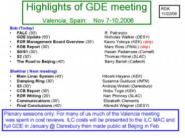
Highlights of GDE meeting Valencia, Spain Nov
7-10,2006
RDK 11/22/06
- Bob (Today)
- FALC (30')
R. PetronzioGDE Update (50')
Nicholas Walker (DESY) - RDR Management Board Overview (35')
Kaoru Yokoya (KEK) (skip) - RDB Report (30') Marc Ross (FNAL) (skip)
- S0/S1 (30') Hasan Padamsee (Cornell)
- S2 (30') Thomas Himel (SLAC)
- The Road to Beijing (40') Barry Barish (Caltec
h) - Shekhar ( Next meeting)
- Main Linac System (40') Hitoshi Hayano (K
EK) - Damping Ring (30') Susanna Guiducci (INFN)
- S3 (30') Andrzej Wolski (Daresbury)
- CCB Report (30') Nobu Toge (KEK)
- RDR Writing (20') Nan Phinney (SLAC)
- Communications (30') Elizabeth Clements
- Final Conclusions (40') Albrecht Wagner (DESY)
Plenary sessions only For many of us much of the
Valencia meeting was spent in cost reviews. ILC
costs will be presented to the ILC MAC and full
GDE in January _at_ Daresbury then made public at
Beijing in Feb
2
FALC
- Was Funding agencies for linear collider
- Now funding agencies for large colliders
- WHY ??
R. Petronzio
3
Global context for particle physics
- Current projects LHC
- RD for the future linear collider / neutrino
facilities / LHC upgrades / CLIC - How do we put these together in a new global
strategy to maximise opportunities
R. Petronzio
4
What to expect from FALC in the medium term plan
- It cannot generate new resources(Governments)
- But it can make a strong case if they are not
sufficient for the realization of global
infrastructures - It cannot replace the scientific debate of the
community (ICFA) - But it can produce the coordination and the
agreements needed to merge local contributions to
a large infrastructure into a unique global
effort
R. Petronzio
5
Composition
- FALC includes representatives from the three
regions - AMERICA
- Canada(NRC) and US(DOE, NSF),
- EUROPE
- CERN(DG and the Council President),
France(IN2P3/CEA), Germany (BMBF),Italy(INFN),Unit
ed Kingdom(PPARC), - ASIA
- Japan(MEXT), Korea (MOST), India, China
- Chairs of ICFA and ILCSC attend
- Started in 2003 and met seven times, across the
regions - Next meeting in KEK, Nov 20
- Note of meetings published on ILC Web page
R. Petronzio
6
ILC specific short term actions
- Appoint an evaluation of the RDR from an external
body such as the ILCSC to give assurance to
governments - Assess the ramp up in efforts needed to match the
TDR phase - Evaluate such an effort within the context of
the whole effort on global infrastructures and
draw conclusions on feasibility.
R. Petronzio
7
GDE (RDR) Update
- Nick Walker
- ILC-GDE
- DESY
8
One year after Frascati
- Frascati 12/05 Snowmass Baseline Configuration
(BC) consolidated and ratified - BC officially placed under Change Control Board
(CCB) control - Many technical details poorly specified (or
missing) - Bangalore 03/06Detailed design reviewed and
iterated planning for cost estimation - RDR Management Board formedBarish, Bialowons,
Garbincius, Raubenheimer,Shidara, Walker
(chair), Yokoya - Weekly videoconferences across Area and Technical
System (AS/TS) set-up - Cost guidelines for TS developed (ETA Value /
CERN Core)
9
One year after Frascati
- Vancouver 07/06Major Goals Achieved after 7
months - Detailed conceptual design
- 90 of cost estimate (WBS) available
- Valencia 11/06Original goal presentation of 1st
draft RDR with cost
10
The Status at Vancouver (July '06)
Baseline Configuration
31 km
14 mr
ML 10 km (G 31.5 MV/m)
RTML 1.6 km
BDS 5 km
2 mr
e undulator _at_ 150 GeV (1.2 km)
R 1.1 km E 5 GeV
x2
not to scale
Configuration used for Vancouver cost
estimate fundamentally no different from Frascati
BC, but much more detail design work
11
RDRmatrix
RDR matrix responsible for technical design and
generating the cost estimate
12
Cost supplied (rolled-up) toArea Systems
13
Regional Cost Engineers responsible for complete
budget book
14
Result of Vancouver
Not! to scale!
- Initial rough cost estimate too high
- Not too surprised
- Begin design and cost iteration
- Identify cost drivers
- Cost estimate not as mature as hoped
- Clear than more time will be needed to push back
on costs - 3 month delay to schedule
- Draft RDRcost to be published atBeijing Feb. 07
15
Approach to Cost Reduction
- Performance driven design
- Identify cheaper machine design (layout)
modifications - Understand Cost Performance trade-offs
- Mostly associated with risk
- Area System Orientated
16
Approach to Cost Reduction
- Review component-level costs
- Identify conservative estimates
- Push back on estimates
- Mass quantity reductions etc.
- Design cost savings
- Simplification of designs
- Cost saving alternatives
- Technical System orientated
17
Approach to Cost Reduction
- Energy
- Luminosity
- Upgradeability
- Least attractive option
- Easiest way to save money!
18
2?14mrad IR
- Vancouver Baseline
- Two BDSs, 20/2 mrad, 2 detectors, 2
longitudinally separated IR halls - Present Baseline
- Two BDSs, 14/14 mrad, 2 detectors in single IR
hall at Z0
- Cost-driven design modification
- 2mr IR significantly more expensive as 20mr
- Immature design
- Discussions with MDI panel
19
Damping Ring
Baseline Configuration
31 km
not to scale
Removal of second e ring
simulations of effect of clearing electrodes on
Electron Cloud instability suggests that a single
e ring will be sufficient
20
Damping Ring
Long 5GeV low-emittance transport lines now
required
Baseline Configuration
30 km
not to scale
Centralised injectors
Place both e and e- ring in single centralized
tunnel
Adjust timing (remove timing insert in e linac)
Remove BDS e bypass
21
Examples of Cost-Driven Design Modifications
being considered
22
Examples of Cost-Driven Design Modifications
being considered
Current decisions are focused on cost baseline
for the RDR Many aspects will be re-evaluated
(iterated) during the post-RDR Engineering Design
Phase This will include evaluation of
Alternative designs as RD becomes mature.
23
CFS A Special Case
- Many significant costs savings identified
- Reduction of number of shafts
- Reduced volume of underground construction
- Impact of schedule being re-evaluated
- 7 years original assumed
- Power/Cooling requirements reviewed
- Dedicted meeting at SLAC (chaired by M. Ross)
- Several cost saving items identified
- and reduction of site power requirement
24
SCRF The Other Cost Driver
- Baseline remains fundamentally unchanged
- baseline gradient 31.5 MV/m
- cryomodule based on TESLA technology
- so-called 4th generation
- Challenge remains high-gradient RD (yield)
- S0/S1 task force (more later)
25
Physics Scope Per Dollar
- Re-evaluating Physics Goals is part of Cost
Awareness - Physics cost drivers
- Energy reach re-defining 500 GeV
- Peak Luminosity
- Single IR (push-pull)
- not directly a physics scope issue
- These will need to be fully discussed and
coordinated with the Physics Detector Community - Physics Parameter Group
- MDI panel
- (WWS)
? Barish Friday plenary
26
Mission of the Global RD Board
- Coordinate worldwide, prioritized, proposal-
driven, RD efforts - The goal is clear, the detailed means required
resolution by the RDB of issues, for example - Level of coordination
- Parallel efforts coordination, Regional needs
- Reviewing role Ideal vs specific RD Program
- Balance ILC/ILC Detectors issues
- Goals, Timelines
- Interfaces, RDB/DCB, RDB/Industrialization
- RDB have already successfully interfaced with US
(DoE) and UK (PPARC) ILC RD proposals.
27
The S RD Task Forces
Priority high
S0 High-Gradient Cavities
S1 High-Gradient Cryomodule
To address priority RD items, RDB has convened
several task forces. S0-S3 will report on
Friday AM GDE plenary
S2 Test Linac
S3 Damping Ring
S4 Beam Delivery
S5Sn
28
Summary
- First iteration design and costs at Vancouver
workshop were too high - Focus of interim period Vancouver-Valencia
focused on cost reduction - Machine design (scope) modifications
- Component level cost reduction
- Physics scope after discussion with Physics
Detector Community - Many design modifications being implemented
- Several proposals rejected by RDR MB
29
Update on S0, S1 for ILC RD
H. Padamsee, Cornell For the S0/S1 Task Force
30
Chair
31
Main Topic of S0 Task Force
- Improve the yield for cavity gradients
- The situation before us
- Proof of principle for 35- 40 MV/m exist
- Single cell results (40 - 50 MV/m) show that
baseline preparation procedures are in hand - But low yield for 35 MV/m in 9-cells
- See the following slides from TTF experience
32
TESLA Nine-Cells (Proof-of-Principle) 9 Best
Cavities (Vertical Test Results _at_low power)
35 40 MV/m
33
Basic Process Works !
World Record! gt 50 MV/m (Cornell / KEK)
Several cavities achieved more than 45 MV/m at
high Q! (KEK)
34
The situation before us TTF Results
- Over the last 11 years, DESY carried out 450
prep/test cycles on 100 cavities, average 40
cycles per year - Important There are many variables in this data
set - Goals
- Cavity gradients, cryomodules, Projects ILC,
TTF-I, TTF-II, XFEL - Materials suppliers
- Heraeus, WahChang, Cabot, TokyoDenkai
- Cavity Vendors
- Dornier, ACCEL, CERCA, Zanon
- Processes
- BCP 1400 C, BCP 800 C, EP 800C, EP 1400
C, Rinsing parameters, Bake, No-Bake - Number of tests/cavity to reach gradients
- For BCP
- finally a nearly production-like operation was
achieved in the 3rd production batch of TTF
cavities, - gt fewer tests per cavity were needed to achieve
25MV/m - For EP
- First an RD phase, many tests per cavity
- First production run ongoing, spread still too
large, many cavities not yet treated second time
35
Synthesis All Cavity Tests
From Lutz Lilje (June 1, FNAL S1 task force
meeting
36
Average Number of Prep/Test Cycles to Reach
Gradient Goal
From Lutz Lilje (June 1, FNAL S1 task force
meeting
37
Where are we now with EP-treated cavities? Best
tests above 34 MV/m - 25Last tests about 27
MV/m - 25Where would be like to be?
38
Ultimate Goal Drafted at BCD
39
Reformulation of BCD - Ultimate Yield Goal
- 80 of cavities reach 35 MV/m on first test
- With 80 yield on second test , the total number
failing is lt 5 - Need a sufficiently large final batch of
cavities to get a statistically meaningful result
40
Present Yield Limitations
- Many tests are still limited by field emission
- Some by quench
- Few by the H-Q disease
- Example Variables to address
- Preparation related
- EP parameters (V, I, S, H)
- Rinsing parameters (time, pressure, water
quality) - Particulate contamination (assembly procedures)
- Fabrication Related
- Cavity production parameters, e-beam welds,
insufficient quality control - Nb material quality (RRR, grain size, defects,
insufficient quality control)
41
A Phased Program for S0With Intermediate Goals
- Separate the task of improving the yield into two
parts - Improve Yield of Final preparation process
- Final EP 10 - 20 um
- HPR
- Bake 100- 120 C
- Test
- Improve cavity fabrication yield (with bulk
processing steps included) - Address gradient limitations from materials
- Address gradient limitations from fabrication
errors
42
Implementation of S0 Part 1Stage 1 Define
Baseline Yield (by mid-2007)
- Find best 9 cavities for tight loop
- Need 9 - 20 cavities at start because yield is lt
0.5 - Send 3 best to lab in each region with existing
full set of facilities - EP-horizontal, H-removal furnace, tuning, HPR,
test - DESY, KEK, Jlab
- Step 1 Qualify HPR and Test stand
- HPR, Assemble Test one high gradient cavity
several times - If not reproducible, improve HPR, cleanliness
- Step 2 Establish baseline for Tight-Loop
- EP/HPR/test, 3 cavities, 3 tests, 3 locations
- Total an 27 tests
- Determine spread
- Step 3 exchange 1 - 3 cavities between regions
for calibration - Total gt 30 tests after qualification
- Use same final preparation procedure at different
sites - (fixed at TTC KEK )
- Use same testing protocol at different sites
- (fixed at TTC- KEK)
43
Implementation of S0 - Part 1 Stage 2 Apply
Process Improvements (by mid-08)
- Inject process improvements from parallel RD
program - see later slides
- Repeat 3 x 3 27 tests
- Compare yield with first set of tests
- Repeat above as necessary
44
Parallel-Coupled RD Plan
- To determine methods that will improve the yield
- Many Arenas of RD Coupled to S0
- Discussed at TTC, Plans Developed
- Single cell prep/tests
- Focus is to remove identified contaminants
efficiently (e.g. sulphur) - Rinsing studies (e.g. ethanol, ultrasound
degrease, peroxide, short etch, HF) - Labs have proposed to participate KEK, Cornell,
CEA Saclay, JLab (inder discussion) - Improved quality control to be implemented
- Process monitoring
- Acid, water QC
- Thermometry diagnostics
- Qualify HPR systems with force sensor system by
INFN
45
Additional Studies
- S-deposition studies in control set ups
- H- contamination studies
- Field emission studies
- Material studies
46
S0 Part 2Work on the Production Yield
- Cavity production yield can be lt 1 due to
- Fabrication errors (e.g. poor welds)
- Material problems (e.g inclusions )
- Troubles with bulk processing stages
- 120 um EP, 800 C hydrogen removal
- Especially important if goals include new vendor
development - May need to decouple if we are tight on cavity
funding, but will have long-range impact - not enough qualified cavity vendors
47
Plan for S0- Part 2
- Plan for production'-like processing of batches
of about 50 cavities each (with some time delay
between them) - For a batch of 50 cavities, statistical error is
about 15 - The staging of these batches should allow for
process improvements obtained from parallel RD
programs, as discussed earlier - During the first production run it is expected
that several tests (up to 3-4) would be
necessary to qualify a cavity to 35 MV/m - In the second and the following ones, the maximum
number of re-test should become progressively
lower - Until the final goal (a total of 1-2 tests per
cavity) is achieved. - Plan to reach ultimate goal by mid-2009 (if
resources available)
48
Implementation of S0- Part 2
- Order a large number of cavities starting as soon
as possible (takes about 9 months to fabricate) - US is preparing to order gt 50 cavities by end
of FY 07 - Globally Order gt 50 in 07 and gt 50 50
cavities by early 08 - Start processing first batch after mid-07 with
best procedure available from tight loop and
basic RD studies (Part I) - Plan for 2-3 production cycles until end 2008
- Final Production batch of 50 cavities (finish
mid-2009) - Use cavities gt 35 MV/m to populate cryomodules
for S1 (later) and S2 (next talk) - How many cryomodules and RF units can we prepare?
49
Additional Scope for Improving Yield for S0- Part
2
- Some labs will work on reject cavities with
diagnostics - Determine nature of defects weld, material
- Feedback to cavity production to improve yield
- Proposals from LANL and MSU
50
Global Capacity for Prep and Testing
Note DESY rate is lower because cavities which
pass 28 MV/m are removed from the cycle for
XFEL Total number of prep/test cycles till end of
2009 gt 420 Tight loop 90 (3 rounds of 30 tests
) Production-like 330
51
S1- Goals
- Achieve 31.5 MV/m (lt 10 drop) at a Q01010 as
operational gradient as specified in the BCD in
more than one module of 8 cavities - including e.g. fast tuner operation and other
features that could affect gradient performance - At least three modules should achieve this
performance. This could include re-assemblies of
cryostats (e.g. exchange of cavities). It does
not need to be final module design. An operation
for a few weeks should be performed. - Intermediate goal
- Achieve 31.5 MV/m average operational
accelerating gradient in a single cryomodule as a
proof-of- existence. In case of cavities
performing below the average, this could be
achieved by tweaking the RF distribution
accordingly.
So far only one cavity ( AC72) has operated at
high gradient in a cryomodule at TTF (RDK note)
52
2006 FLASH Module 6 High Gradient Module
- This module serves two purposes
- Demonstration of high operational gradient
- Industry and partner labs to participate in
assembly process - Average of horizontal tests gt 32 MV/m
CM6 will be first high gradient module TTF
summer 07 (RDK note)
53
Conclusions
- S0, S1 goals defined
- Work plans exist (S0, Single-cells) or are being
formulated (S1) - Tight loop Work started in Japan and US
- DESY is in a production-mode, tight-loop options
being discussed - RD for improved process on-going in all regions
- Next steps for S0 Task Force
- Compare cavity plans worldwide with target scope
- Resolve gaps
- Stretch schedule to 2010 TDR impact
- Reduce scope end up with larger spread than
target - Get more RD support with help from GDE.
- RD Board is discussing options for tracking
progress of S0/S1 - e.g. full-time person for
- tracking, data integration, communication,
comparing systems performance, supporting process
improvements over lab boundaries - Evaluate cost/performance benefits of S0/S1
54
S2 Task Force Status(String test definition)
- Tom Himel
55
Overview
- Task force set up by the Global RD board
- What are the reasons and goals of a system test?
Start with TRC R2 list. - Determine how many RF units are needed as a
system test before ILC construction - Do they need to be in a string?
- Is beam needed?
- We were just getting started in July at the
Vancouver meeting - Nearly finished now. Expect final report by
early January.
56
Members
- Hasan Padamsee (Co-Chair)
- Tom Himel (Co-Chair)
- Bob Kephart
- Chris Adolphsen
- Hitoshi Hayano
- Nobu Toge
- Hans Weise
- Consultants Sergei Nagaitsev, Nikolai Solyak,
Lutz Lilje, Marc Ross, Daniel Schulte
http//www.linearcollider.org/wiki/doku.php?idrdb
rdb_externalrdb_s2_home
57
Process
- Followed 2 paths
- What do we want to test in a system test? How
big a system is needed for each test? Is beam
required? Has it been done or can it be done at
TTF? - What is the scale of the industrial effort and
how will this provide a smooth transition to the
start of main linac construction? Do the modules
produced in this effort need a system test or
does it produce so many RF units that we may as
well use them in a system test? - Then compared results and made an overall plan
58
The LIST
- Made a list of things that needed testing.
- Started with TRC R2 list.
- Spreadsheet with full list of 31 items is on our
wiki page. - Some items only need testing because of changes
made or planned since TTF. - Not all items MUST be tested. There is a
cost/risk trade-off to be considered.
59
The LIST Items too big to be practical
- Checking that DFS steering really controls the
emittance growth would take well over 10 RF units
with best RF gun as beam source. - A full check of cryogen flows and controls
requires a 2.5 km string (partial test can be
simulated with much less) - Checking that cavity misalignments dont cause
emittance growth
60
The LIST Statistical effects where more is
better and enough is too many
- Checking reliability is as good as required could
require full ILC. - Some aspects best tested in standalone stress
tests (tuner motors, feedthroughs) - Dark current
- Depends on statistics of number and location of
emitters. - Can calibrate and check simulations of
radiation/heat load due to captured dark current. - Long term testing of cryomodules to evaluate
degradation or other weaknesses before large
scale series production begins - e.g. HOM failures in SNS caused by end wall
heating due to field emissions. TTF has seen no
degradation. - We cannot for-sure find all potential problems,
but can reduce the phase space
61
The LIST Items that can be fully tested
- Check what gradient spread can be handled by LLRF
system. This test should be done with and without
beam loading. - Check for heating due to high freq HOMs
- Check amplitude and phase stability
- Check static and dynamic heat loads
- Note that all of the above can be done with 1 RF
unit
62
The LIST Most important reasons for a system test
- Do a system integration test with near final
components and full gradient to demonstrate it
works. - Check for alignment problems caused by forces
from the cryomodule interconnect. - Check for beam deflections and cryo-load from
HOMs (both trapped and propagating).
63
Industrialization needs
- Looked at how previous high tech projects have
been industrialized - Made sample cavity/cryomodule industrialization
plans - Counted how many cryomodules we may have as a
function of time. - Industrially produced cryomodules will clearly
have to be tested either individually or in a
system test. - With present plans to industrially produce
cryomodules in all 3 regions, test facilities
will be needed. - At least one test facility will need ILC like
beam.
64
Industrialization timing
- Looked at industrialization of SSC, RHIC, LHC
magnets and LEP cavities - Some items we looked at were industrialized well
before project approval. SC wire and Niobium
sources for cavities are examples of this. - Some items we looked at were prototyped in the
labs and transferred to industry after project
approval. LEP cavities and all the magnets are
examples of this. - It is yet to be decided how ILC cryomodules will
be industrialized. Suspect S2 will be reconvened
to make these plans. We have not considered the
size of facilities needed to test the production
cryomodules.
65
S2 DRAFT conclusions
- The TTF facility at DESY has provided a valuable
system test of many elements of the ILC
technology. More tests can and should be
performed there. The XFEL will also provide
valuable experience. - However, several important changes to the TTF
design are being planned for the ILC. These
include a higher gradient, relocation of the
quad, shortening of the cavity end-group, and a
new tuner design. Also under discussion are
different modulators, klystrons, cavity shapes,
and other things. - The minimum size system test needed to confirm
the performance of such a new design is a single
RF unit (3 cryomodules) with ILC like beam. As
many tests are statistical in nature, a larger
test or multiple tests would be better.
DRAFT
66
S2 DRAFT conclusions
- All three regions have expressed a desire for
command of basic ILC SCRF technology and are
preparing to manufacture cryomodules locally.
Local test facilities at the scale of 1 RF unit
are under construction in Asia and the Americas.
In addition to TTF and XFEL, Europe has submitted
an expression of interest for an ILC RF unit test
facility at CERN. - As construction of the project starts, a larger
second phase system test will be needed to check
the final manufactured components. One of the
possible scenarios is to build a test linac with
contributions of a total of several RF units from
the three regional teams of the final
consolidated ILC linac system design. It is S2s
intention to make recommendations on the suitable
scale of this effort by the time of its final
report.
DRAFT
67
Rough Schedule
68
Road to Beijing and Beyond
- Barry Barish
- Caltech / GDE
- 10-Nov-06
69
Vancouver Costs for BDS
Total Cost
- Cost drivers
- CFS
- Magnet system
- Vacuum system
- Installation
- Dumps Collimators
Additional costs for IR20 and IR2
70
Valencia Reviews
Focus on completeness of design and cost status
- Wednesday Area System
- Main Linac
- BDS
- RTML
- DR
- ee- sources
- Thursday Technical
- RF Power Dumps Collimators
- Instrumentation Magnets / Power Supplies
- Cavities / CM Controls (LLRF)
- Vacuum Installation
- Metrology Cryogenics
Focus on component cost estimates, cost reduction
and quality/basis of estimate
71
Initial (Management) Feedback
- Very impressed by standard of presentations
- and amount of work done!
- We need a little more time (week) to consolidate
and review cost savings - synchronise area system technical groups cost
engineers cost information - check for double counting effects etc.
- The cost of the machine is significantly less at
the End of the Workshop than at the Beginning
72
Findings
- Significant cost reductions for many groups
- Good progress in completing estimates, WBS
dictionary and Basis of Estimate - watch out for double counting the savings, easy
for both Area Systems and CFS to take credit - Still missing much institutional labor estimates,
but found some hidden labor as costs some
confusion on labor need guidance
73
On Tuesday, Tetsuo showed
- Our efforts at Valencia identified another 4.91!
74
MDI Related Design Changes
- Some cost / performance design changes would
affect physics performance or reach. We are
trying to pick items without major impact or are
reversible changes - Energy reach maintain 500 GeV (but redefine
performance at that energy) - Peak Luminosity (reduce for initial running
but, upgradeable) - Two detectors preserved, but one beam line
push-pull - These are being fully discussed and coordinated
with the Physics Community - MDI Panel WWS Physics Parameter Group
75
Push-Pull Evaluation
- Initiated by GDE WWS at the end of September
- Detailed list of questions to be studied
developed - Large group of accelerator and detector
colleagues, from ILC and other projects, is
participating in design and discussion of these
question - The task force of detector experts was formed to
contribute to detailed evaluation of the whole
set of technical issues
http//www-project.slac.stanford.edu/ilc/acceldev/
beamdelivery/rdr/docs/push-pull/
76
Reduced Bunches
Impact of ILC operation with a reduced number of
bunches Introduction As a possible cost
reduction option, a proposal to operate with half
the number of bunches (approximately 1330
bunches) over the same train length (one ms) is
being considered. Because of a factor of two
reduction in the size of the RF system, this
modification will result in a net savings of 2-3
of the total project cost. Although the peak
luminosity of the machine will be reduced by a
factor of two, a relatively straightforward
upgrade of the RF system can fully restore the
machines luminosity performance to that of the
current baseline.
77
Luminosity Model ½ RF Scenario
tor
78
Plans until Beijing (Feb. '07)
- By the end of this workshop we must have
- consolidated design
- new cost estimate
- prioritized plans for addressing remaining
(cost-driven) issues - schedule for CCB
- Clear guidance and goals for writing the RDR
79
ILC Documents
Phinney
- Several reports for different audiences
- Brochure non-technical audiences, ready now
- Quantum Universe level booklet 30 pages
- Executive Summary 30 pages
- Physics motivation, accelerator and detectors
- RDR Report 300 pages
- high level description of the accelerator
- DCR Report 250 pages
- physics and detectors
80
RDR Report
Phinney
- RDR is a high level description of the
accelerator, CFS, sites and costs - A snapshot of what we propose to build
- not a history of RD, design evolution, and
alternatives - Editors
- Nan Phinney (SLAC), Nobu Toge (KEK), Nick Walker
(DESY) - Original schedule was complete draft now, but has
been pushed back because of cost iterations
81
New RDR Schedule
Phinney
- Now
- Document and most section outlines in hand,
editors to iterate content with section authors - mid-Dec
- 1st drafts of Executive Summary and all area,
technical and cost sections - early Jan
- Complete draft for review by ILC MAC and
discussions with funding agencies - Feb
- Draft available in PDF and on web, pending final
revisions before publication - Summer 07
- Published version
82
Following MAC Review
- RDR / Costs will remain internal until Beijing
- This period will enable us to take into account
immediate feedback from the MAC - This period will enable us to give advance
briefings to FALC, FALC Resource, ICFA members,
government agencies, etc - Final Approval by GDE at Beijing and submit to
ICFA - ICFA meetings on 8-9 Feb 07
83
Plans until Beijing (Feb. '07)
November
December
January
February
2006
2007
Valencia
Further cost consolidation CCR preparation
submission
Cost Design Freeze 30/11
Prepare for Full Cost Review
SLAC Cost Review 14-16/12
Final cost corrections and documentation
MAC 10-12/01/07
Agency cost briefings
Beijing RDR draft published
84
What Happens after Beijing?
- Public Release of Draft RDR and Preliminary
Costing at Beijing - Cost Reviews, etc
- Finalize RDR by Summer 2007?
- Enter into Engineering Design Phase
- Planning underway internally (B Foster talk)
- Probably some reorganization of GDE to include
stronger project management and work package
responsibility. - Design will evolve through value engineering and
RD program (value engineering RD results etc) - Cost of EDR will be consistent with RDR
- General Goal is to have Construction Proposal
ready by 2010
85
Conclusions
- Design decisions for RDR almost all in place
- We are approaching cost goals
- Writing of RDR and companion document getting
underway. - We expect to make our goal of releasing RDR and
costs at Beijing - Post Beijing planning is underway
86
Shekhars part