
Capstone CDR - PowerPoint PPT Presentation
1 / 35
Title:
Capstone CDR
Description:
Time Chart. Milestone Tasks. Freddy. CCD Parallel Interface. CCD ... Purpose: Conversion from CCD analog output to FPGA A-2 header. Module 4 : Spartan III FPGA ... – PowerPoint PPT presentation
Number of Views:56
Avg rating:3.0/5.0
Title: Capstone CDR
1
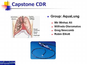
Capstone CDR
- Group AquaLung
- Mir Minhaz Ali
- Wilfredo Oteromatos
- Greg Newcomb
- Robin Elliott
2
Presentation Overview
- Freddy
- CCD Parallel Interface
- CCD Serial Interface
- Functional Block Diagram
- Analog to Digital
- FPGA Connection
- Minhaz
- Hardware Overview
- Bill of Materials
- Fiber and Camera Assembly
- CCD and Connection
- Greg
- USB Interface
- Easy USB Chip
- Connection
- Device Driver to handle USB
- Driver to GUI
- Robin
- Software Functionality
- Software Flowchart
- AquaImage
- Program Launch and Menu
- Time Chart
- Milestone Tasks
3
Complete Hardware Overview
4
Bill of Materials (BOM)
- 1 meter long optical fiber with built in camera
- Ti CCD Sensor (TC237B)
- Hi speed clock driver for CCD (EL7202C)
- Octal buffer for CCD serial driver ( 74ACT240NS)
- Spartan 3 FPGA with 1M-byte of Fast Asynchronous
- USB Chip (FT245BM)
- USB Cable and connector
- 8bits ADC(AD7825)
- EPROM (93LC46B-I/P)
- Clock (12.5 MHz) (CSTLS6M00G53Z-B0)
- Crystal Resonator (6MHz)
- Variable output voltage regulator (PTN7800)
- Other hardware, Capacitor and resistor.
5
Optical Fiber and Camera
- 7000 pieces of fiber inside creating full color
image. - 0.5mm diameter glass fiber imaging bundle enables
scope to bend around . - Very inexpensive(120) for 1M long fiber with
camera - 2 Xeon light bulbs to illuminate the image.
1M long Optical Fiber
Camera Tip
Eye Piece
6
Charge Couple Device (CCD)
- 0.34M Pixels Per Field
- 658(H) x 469(v) Active Elements
- Multimode readout capability
- Progressive Scan
- Duel Line readout
- Image Area line Summing
- Low Dark Current
- 7.4µm x 7.4µm pixel size
- 12.5 MHz Clock
7
Module 1 CCD
- Four Functional Blocks
- Image sensing area
- image storage area
- serial register gate
- low noise signal processing amplifier block
- The storage area and serial gate are used to
transfer charge line by line from storage area
into serial register - After transfer the pixel are clocked out and
sensed by charged detection node.
8
Module 2 CCD Parallel interface
- Drivers
- EL7202C (non-inverting)
- Image Area Gate (IAG)
- Storage Area Gate (SAG)
- - Input CLK(12.5MHz)
- Output Logic signals to control Image and
Storage Areas. - Purpose Activates the Image Area and Opens the
Storage Area.
CCD Driver
9
Module 3 CCD Serial Driver
- Progressive Scan Mode
- Two register available for high speed data
transfer - Drives the Serial Register Gate (SRG)
- 12.5Mhz clk. Signal.
- 74ACT240 Octal buffer
- Allows data to be pulled from the serial
registers. - Input CLK (12.5MHz)
- Output Driving signal.
Octal Buffer
10
Functional Block Diagram
Parallel Driver
Serial Driver
11
Analog to Digital Converter
- AD 7825
- 2Msps
- 420nS conversion time
- PWR Dissipation 36mW
- Input 2 AC signals from CCD out1 and 2.
- Output 8 Bits Parallel to FPGA.
- Purpose Conversion from CCD analog output to
FPGA A-2 header.
12
Module 4 Spartan III FPGA
- FPGA Spartan III
- Inputs
- Data from ADC
- End of Conversion (EOC) signal from ADC.
- Outputs
- 8 bits data to USB interface
- Control signals to
- ADC
- USB (interface)
- CCD
- Function Data timing issues resolutions and
sampling.
13
Module 5 USB Interface
14
Easy USB chip
- FIFO Interface between FPGA and USB cable
- Bidirectional
- Transfer data rate 1M byte/sec
- Entire USB protocol handled on-chip
- Simple to interface with FPGA
- USB 2.0 Compatible
- Cheap
- EEPROM optional (93LC46B)
- Default setting or program with EEPROM
- 6 MHz Timing Chip required (CSTLS6M00GS32-B0)
- With 8x clock multiplier, works at 48 MHz
15
Easy USB - FT245BM
Single Chip USB ltgt parallel FIFO bi-directional
data transfer
Clock
EEPROM Interface
Check TXE Low
Control
16
Easy USB - FT245BM
Single Chip USB ltgt parallel FIFO bi-directional
data transfer
Clock
Input 8 pin digital signal from FPGA (D0-D7)
EEPROM Interface
Write when TXE Low
Control
17
Easy USB - FT245BM
Single Chip USB ltgt parallel FIFO bi-directional
data transfer
Clock
Input 8 pin digital signal from FPGA (D0-D7)
EEPROM Interface
Sending over USB cable
Output 2 pin signal to USB Cable (USBDP USBDM)
TXE is Raised
Control
18
Easy USB - FT245BM
Single Chip USB ltgt parallel FIFO bi-directional
data transfer
19
Physical Connection to USB pins
To PC
From FPGA
Type A/B USB cable
Pin FPGA Signal Name
1 5 V VBUS
2 USBDM Data Minus
3 USBDP Data Plus
4 GND GND
20
USB Cable
- USB 2.0 (Full Speed)
- Uses NRZI (Non Return to Zero Invert) encoding
- Not our problem!
21
Device Driver to Handle USB
- Provided by FTDI free
- Version for Windows XP
- Will allow for plug play
22
Driver to GUI Handoff
Notice Interrupt Open File 1
23
Driver to GUI Handoff
Save 1st picture
24
Driver to GUI Handoff
Notice File 1 is Full Open File 1
Picture 1 saved Close File 1
25
Driver to GUI Handoff
Read Data from File 1
Save next picture
26
Driver to GUI Handoff
Finish Getting Data Close File 1
Save next picture
Send image to monitor
27
Driver to GUI Handoff
Open File 2 Get Data
Save next picture
28
Software Functionality
Pick Up Event
Launch Program
Display Moving Image
Y
- Option
- Buttons
- Zoom
- Color Contrast
- Pause/Unpause
- Auto Save
- OpenSaved Image
Data?
N
Pick Up Event
Display Still Image Or None at all
Exit Program
29
Software Flow Chart
? Valid Mouse Event ?
- Display Moving Image
- Patient name ID
- Zoom/Contrast toggle
- Zoom Level (if zoomed)
N
? Determine Event ?
- Launch Program
- initialize software
- look for device driver
Y
? Image Update Ready ?
Y
N
Y
? Device Driver Found ?
? Data From Driver ?
- Auto Save Image
- Name, ID, date, time
Y
Y
? Moving Image ?
- Zoom Toggle
- Turn off Color Contrast
N
- Color Contrast Toggle
- Turn off Zoom
N
Display Driver Error
N
Unpause the Image
Display No Signal
Pause Current Image
Open Saved Image
? Open Saved Image ?
? Determine Event ?
Y
- Display Still Image
- Patient name ID
- Zoom/Contrast toggle
- Zoom Level (if zoomed)
? Valid Mouse Event ?
Y
N
N
- Exit Program
- Close all files
- Exit
- Confirm
30
About AquaImage
This is the About box seen in all Windows
applications.
31
Program Launch
- Screen seen at start-up.
- Circled items are customized features.
32
Menu Bar
- Menu features included in AquaImage.
33
Time Chart
34
Milestone Tasks
- Milestone 1
- GUI Complete
- Device Driver Implemented/Not Tested
- Prototyping and Modular Testing
- Milestone 2
- Static Interface Working
- Prototyping and Testing Complete
- PCB In House
35
Questions ??
Recommended
CrystalGraphics Presentations


