
NuMI Hot Handling - PowerPoint PPT Presentation
Title: NuMI Hot Handling
1
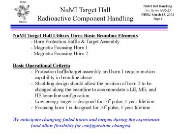
NuMI Target HallRadioactive Component Handling
NuMI Target Hall Utilizes Three Basic Beamline
Elements - Horn Protection Baffle Target
Assembly - Magnetic Focusing Horn 1 - Magnetic
Focusing Horn 2 Basic Operational Criteria -
Protection baffle/target assembly and horn 1
require motion capability in beamline
chase - Shielding design should allow the
position of horn 2 to be changed along the
beamline to accommodate a LE, ME, and HE
beamline configuration - Low energy target is
designed for 107 pulse, 1 year lifetime -
Focusing horn 1 is designed for 107 pulse, 1 year
lifetime We anticipate changing failed horns and
targets during the experiment (and allow
flexibility for configuration changes)
2
NuMI Target HallRadioactive ComponentHandling
Considerations
Additional Design Specifications - Positioning
mechanism (i.e. module) should be reusable -
Main consideration is component change-out
capability - Secondary consideration is for
very limited repair capability (e.g.,
repairable water leak on a component with
relatively low residual activation
level) - Require a spent component storage area
3
NuMI Target HallRadioactive ComponentHandling
Approach
Considering Previous Criteria and
Specifications - NuMI has decided to design the
NuMI Target Hall based upon the AP0 Target Hall
approach to positioning and handling beamline
components - This technique has worked well for
the past 16 years in terms of providing for
beamline component servicing and change-out while
controlling radiation exposure rates to target
hall operations personnel
4
Radioactive Component HandlingAP0 (not NuMI)
Target VaultRemoving Module Filler Plates
5
Radioactive Component HandlingAP0 (not NuMI)
Target VaultMoving Target Module to Work Alcove
6
Radioactive Component HandlingAP0 (not NuMI)
Target VaultTarget Module Stored in Work Alcove
7
NuMI Target HallBeam line is below floor level
Temporary Stackup of removed shielding Steel
from module middle Concrete from over horn
HornModule in transit Stripline
Concrete Cover Module Support Beams
Horn Shielding Module Horn Steel Shielding
Air Cooling Passage Concrete Shielding
Beam passageway (chase) is 1.2 m wide x 1.3
high
8
Target and Horn ModulesNuMI module 2 AP0
modules cross-bracing walls
Motor drives for transverse and vertical motion
of carrier relative to module
25 cm wide, 2 m deep Steel endwalls with
positioning, water, electric feedthroughs
Target/Baffle Module
Horn 1 Module
Remote Stripline Clamp
Stripline
Baffle
Carrier
Water tank
Target
Horn 1
Target moves relative to carrier for
insertion into horn for L.E. beam
9
Shield T-Blockfor remote insertion in module
- Prototype T-block (inserts in module, but rests
on shield walls). - tested remote
- handling with
- camera on
- crane hook
10
NuMI Target Hall
11
Lifting Tablein Hot Cell
Push horn or target up into module remotely
5 degrees of motion
Each table has independent vertical and
transverse motion
Both tables move together along beam
direction
12
Hot Handling Work CellMount/dismount components
on modules
Horn mechanical connection to module, remote
stripline clamp, waterline connection to
horn, electrical connection to horn
are all done through the module by person on top
of hot cell
Railing Module Lead-glass window
Horn Remote lifting table Concrete walls
3 m
13
Lifting Fixture for ModuleRemotely change pick
point to match center of gravity
Teeth engaged at center of gravity for
horn 1 pick
Teeth disengaged to enable movement of hook
relative to lifting fixture frame
Lifting fixture box frame Module hook
Pins to engage module hooks
14
Hot Horn Replacement Procedureitalics denotes
remote operation (camera)
- Remove concrete cover, use to build temporary
shield - Disconnect utilities from top of module
- Crane the shield T-blocks from module to
temporary shield pile - Crane modulehorn to hot cell (close cell door,
place covers on top) - Disconnect utilities through module, loosen horn
attachment - Lower horn with lifting table
- Crane hot module out of way (back in chase)
- Crane hot horn to Morgue (hot horn storage area),
cover - Crane new horn in Hot Cell
- Crane hot module to hot cell
- Insert horn onto module with remote lifting table
- Connect horn utilities through module
- Crane modulehorn back into beamline
- Insert shield T-blocks into module
- Connect utilities to top of module
- Replace concrete cover
15
Hot Handling Dosefor hot horn replacement
Note 1 sievert 100 rem
Recommended
CrystalGraphics Presentations


