
Associative Tray and Tooling Design - PowerPoint PPT Presentation
1 / 13
Title:
Associative Tray and Tooling Design
Description:
Associative Tray and Tooling Design. Using WAVE Geometry ... Sherpa Design, Inc. CAD Junkie. My Background. Castings, tooling/fixtures, plastics, electronics ... – PowerPoint PPT presentation
Number of Views:24
Avg rating:3.0/5.0
Title: Associative Tray and Tooling Design
1
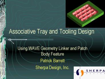
Associative Tray and Tooling Design
- Using WAVE Geometry Linker and Patch Body Feature
- Patrick Barrett
- Sherpa Design, Inc.
2
Who Am I?
- Patrick Barrett
- Sherpa Design, Inc
- CAD Junkie
- My Background
- Castings, tooling/fixtures, plastics, electronics
- Low to High-end design, design automation
- UG, Pro/E, SolidWorks CAD packages
3
Our Challenge
- Design formed-fiber trays for apple packing
- Variable pocket and edge radii
- Variable pocket counts
- Design and build tooling to produce
- 7 different tools per tray
- Different materials for each tool
- Shrink factors, assortment of offsets and
clearances - Make it associative re-use it again
4
The Process and Our Approach
- Tray designed, prototyped
- Fit, support of fruit
- Designed at finished tray size
- Tooling designed
- Shrink factors during drying applied
- Separate/unrelated part files? (old way)
- Lets do this smarter
- Changes to tray changes to tooling
- Tray model drives tooling models
5
UG Tools We Used
- Assemblies
- Still got individual part files
- Clone Assemblies for future tray designs
- WAVE Geometry Linker
- Linked Region inside or outside surface of tray
- Could do what we wanted in tooling files and it
would update - Patch Body
- Tray surface to die base
- Independent changes
6
Assemblies
- Work in individual part files yet maintain
associativity between components - Lets us use the Parts List in B.O.M
- Part attributes can be changed at component level
- Need to have assemblies to use WAVE tools
- Can assemble Empty Parts to begin modeling
- Reference Set management
7
WAVE Geometry Linker
- Note edit ug_english.def file to allow interpart
expressions if its your first time - Similar to Extract feature
- Lots of options depending on your need
- Faces, curves, sketches, bodies, etc.
- Toggle between Work Part and Displayed Part to
link assembly geometry
8
Patch Body Feature
- Booleans a Sheet Body and a Solid (or sheet)
- Trim/Unite/Sew functionality
- Good when surface normals cause trim problems
- Need overlapping edges or loose tolerance
- Very handy with complex surfaces
1) Select Solid Body to Patch To
2) Sheet Body to Patch With
9
Simple Cup and Pin Demo
- Assemblies, WAVE Geometry Linker, Patch Body
10
How We Applied This
- Modeled tray
- Assembled in tooling file
- Linked regions of tray we needed
- Inside or back face depending on tool being
designed - Traverse Interior Edges selected
- Applied shrink
- Patched tray region with tooling bases
- Offset faces, added clearance as required
11
Tray and Female Wire Die Demo
- Modify Tray Design and Changes Are Passed to Wire
Die Tool
12
Results
- All tooling files are driven by the same tray
model - Changes are made once, and updated in all related
parts - Linked region grabs everything inside boundary
- What used to take 2-3 weeks now takes a couple
days - Next step tray design can still be improved upon
13
Questions
- Patrick Barrett
- pbarrett_at_sherpa-design.com
- 503-771-3570
- www.sherpa-design.com
Recommended
CrystalGraphics Presentations


