
OEM identification - PowerPoint PPT Presentation
1 / 46
Title:
OEM identification
Description:
19.05mm NPT thread standard or optional 15.875mm OD polytube nut connection. ... HARDNESS: Adjustable from 1-150 degrees D. Default is 19. Press NEXT ... – PowerPoint PPT presentation
Number of Views:29
Avg rating:3.0/5.0
Title: OEM identification
1
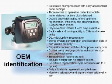
OEM identification
- Solid state microprocessor with easy access front
panel settings - Three modes of operation meter immediate, meter
delayed, or time clock delayed - Double backwash ability, offers optimum
regeneration, efficiency and cleaning ability - Regeneration cycles
- Days override feature 1 28 days available
- Backwash and brining ability to 559mm diameter
tanks - Downflow/upflow regeneration
- Stores system configuration and operation data in
non volatile memory - Capacitor back-up with two hour power carry over
- Control valve design provides optimum service and
backwash rates - Treated water regenerant refill
- Modular design with no screws to lose
- Selectable regeneration cycle sequence (up to 9
cycles) - Fully adjustable regeneration cycle times
- Monitors salt usage and signals when salt level
is low
2
Specifications
- Service 102 lpm _at_ 1 bar drop with meter and
bypass installed. Backwash 102 lpm _at_ 1.7 bar drop
with meter and bypass installed - Comes with 4.572 m cord
- 26.67mm distributor tube cut-off height is 12mm
top of tank - Materials suitable for most regenerants.
- Easy locking drain/brine clip for easy removal.
Orient in any direction.
3
Bypass
- Directional shut-off arrows Normal, Bypass,
Diagnostic mode, Shut-off mode. - Radial seals handle side-to-side and up/down
minor plumbing misalignments, connections need
only hand tightening. - One internally lubricated O-ring on rotor creates
less friction.
4
Fitting packages
- 19.05mm and 25.4mm brass sweat adaptors.
- 25.4mm NPT PVC 90o.
- 19.05mm and 25.4mm PVC Solvent 90o.
- 25.4mm and 31.75 Noryl NPT straight
- 25.4mm Noryl BSPT straight
- PVC fittings standard with 6.35mm drill out
feature. - 6.35mm drill out feature can be used as a sample
port or R/O connection.
5
Six levels of programming/display information
- Homeowner/user screens.
- Installer screens.
- OEM softener or filter system setup screens.
- OEM regeneration sequence screens.
- Diagnostic screens.
- Valve history screens.
- Information is specific to each
programming/display level. - Lockout feature only allows access to homeowner
and installer screens.
6
Regenerant refill
Flow valve
- Backwash plug is used to convert softener to
backwash only filter.
- Locking clip for easy removal.
- Brine elbow available for 9.525mm and 12.7mm OD
tubing.
- BLFC 1.89 lpm refill only (flow valve closes in
refill and opens when drawing, allowing greater
draw rate).
7
Drain fitting
- Easy locking clip removal. Orient in any
direction. - Silencer injects air for quiet drain running.
- 19.05mm NPT thread standard or optional 15.875mm
OD polytube nut connection. - Brine and drain fittings cannot be interchanged
(Prevents misapplication). - 19.05mm fitting 13 DLFCs from 2.7 to 37.9 lpm.
Silencer
- 25.4mm fitting 8 DLFCs from 34.1 to 94.6 lpm.
- Washers easy to replace.
Silencer
8
Meter
- Measures from 0.9 to 102 lpm 5 accuracy.
- Hall chip picks up magnetic pulse. Softening or
Filtering, display flashes when drawing water. - Easy to replace turbine.
- Shielded magnet.
Hall chip
Magnet
9
Easy access
Capacitor
- Drive bracket modular design allows easy access
to components
- Capacitor back-up with two-hour power carry over.
10
Drive Motor Removal
- Disconnect motor power wire from microprocessor.
- Pull out motor.
- Press motor locking clip to the right.
- Rotate motor to a point where wire connections
are in a vertical position.
11
Removing the Microprocessor
- Remove power and meter cable from microprocessor.
- Pull top of microprocessor forward.
- Press up on locking tab.
12
Removing the Drive Bracket
- Remove power and meter wires from drive bracket
retainer.
- Lift up on the two tabs as indicated.
- Pull top of drive bracket forward, using finger
tabs.
13
Removing the Gear Box
- Remove gear box by pressing beige clip.
- Gears can be removed by sliding off post.
- All three gears are identical.
14
Removing the End Cap
- Unscrew drive assembly with wrench.
15
Brine Piston
- Brine Piston is easily removed with a snap lock
connection. - Brine Piston is not used with backwash only
filter.
16
Main piston
Cavity
- Main piston is attached to piston rod with a
snap-off connection.
- Put a slight side pressure on piston at the
cavity to remove.
- To remove piston rotate white gear to expose
piston.
17
Upflow and Downflow controls
- A separate valve body and piston are used for
upflow and downflow brining controls.
18
Downflow Valve Body and Piston
- Downflow body is identified first by removing the
injector cap - The letters DN and UP will be visible
- The injector will be in the DN hole
- A plug will be in the UP hole
- Downflow piston is a solid amber color.
19
Upflow Valve Body and Piston
- Upflow body is identified first by removing the
injector cap - The letters UP will only be visible
- The injector will be in the UP hole
- A plug will be in the other hole
- Upflow piston is a black and amber color
20
Spacer Stack Assembly
- Spacer stack assembly is removed by simply
pulling out.
21
Spacer Stack Assembly
- One-piece disposable assembly.
- Assembly is designed to compress and seal when
tightening end cap.
22
Injector Cap Removal
- With wrench or pliers, remove injector cap.
23
Injector Cap and Screen
- Injector screen pulls out of cap for easy
cleaning.
24
Injector position
- Injector is placed in brine flow direction hole
DN - downflow brining UP - upflow brining. - A plug is used in the other port.
- Picture displays a valve for downflow brining.
- Note If converting a valve the appropriate
upflow or downflow main piston must be used.
25
Injector Sizes
- Injectors are color coded for easy
identification. - Injectors are available for 152mm - 559mm tanks
on downflow brining softeners, or 203.2mm - 559mm
tanks on upflow brining softeners.
26
Injector Plugs
- When shipped from the factory as a backwash only
filter, the brine piston and injector will not be
included. (Plugs are used to block injector
passages.) - If field converting from a softener to a backwash
only filter, only a backwash plug is necessary. - Note If the brine piston is left in the control
when converting to a backwash only filter, the
injector must also be left in.
27
Programming Screens
28
User Screens Time of day, Gallons/Days Remaining
Button Functions
Set time Escapes and saves changes in
programming modes
Toggles between capacity, time, and pounds of
salt Move to the next display in programming mode
Change variable being displayed in programming
mode
Toggles scheduled regen on/off Hold for more than
3 seconds starts immediate regen Backs up 1 step
in programming mode
29
User Screens Time of day, Gallons/Days Remaining
Capacity Remaining Set up to regen by gallons
Capacity Remaining Set up to regen by days
Softening or filtering flashes when turbine is
rotating
Press NEXT to see current time
Press NEXT again to return to Capacity/Days
Remaining
30
User Screens Time of day, Gallons/Days Remaining
Regeneration screen
Set clock
- Press SET CLOCK
- Adjust hours with up/down arrows
- Press NEXT
- Adjust minutes with up/down arrows
- Press NEXT to return to normal operation
Displays time remaining in current regeneration
cycle
31
Installer Screens Hardness, Day override, Time
of regeneration
Installer screens are accessed by pressing NEXT
and the UP arrow
32
Installer Screens Hardness, Day override, Time
of regeneration
- One of these four screens will appear, depending
on setting in OEM cycle sequence
- HARDNESS Adjustable from 3-2500 ppm. Default is
342 ppm. - Press NEXT
- HARDNESS Adjustable from 1-150 degrees D.
Default is 19. - Press NEXT
- Using -nA- will not allow the control to
calculate volumetric capacity. It is placed
directly in place of ionic capacity in
Service/OEM screens. - Press NEXT
- HARDNESS Adjustable from 1-250 degrees F.
Default is 34. - Press NEXT
- If using a mixing valve, set the amount of
effluent hardness using the UP or DOWN buttons. - PRESS NEXT
- (Continued on next slide)
33
Installer Screens Hardness, Day override, Time
of regeneration
- DAY OVERRIDE Off or 0-28 days. Default is 14
- Press NEXT
- TIME OF REGENERATION Set hours. Default is 2
a.m. (If on 0 is set in set up, regen will be
immediate if total capacity is exhausted, and
---- will be displayed.) - Press NEXT
- Set minutes
- Press NEXT to return to normal mode
SET CLOCK saves changes and escapes to normal
operation from any programming screen
34
OEM Cycle Sequence Screens
OEM Cycle Sequence screens are accessed by
pressing NEXT and DOWN for three seconds...
and then pressing NEXT and DOWN simultaneously.
35
OEM Cycle Sequence Screens
- Select hardness measurement by pressing the UP or
DOWN buttons. The four choices are degrees F,
degrees D, ppm or -nA-. Using -nA- will not allow
the control to calculate volumetric capacity. It
is placed directly in place of ionic capacity in
Service/OEM screens
- Press NEXT
- If using a mixing valve, set the amount of
effluent hardness using the UP or DOWN buttons. - PRESS NEXT
- (Continued on next slide)
36
OEM Cycle Sequence Screens
- CYCLE 1 Set first cycle
- Press NEXT
- CYCLE 2 Set second cycle
- Press NEXT
- CYCLE 3 Set third cycle
- Press NEXT
- CYCLE 4 Set fourth cycle
- Press NEXT
- CYCLE 5 Set fifth cycle
- Press NEXT
37
System Set Up Screens
System set up screens are accessed by pressing
NEXT and DOWN for 3 seconds
38
System Set Up Screens - Softening
- SOFTENING OR FILTERING Default is softening
- If Softening is chosen, the following programming
screens will occur. - Press NEXT
- CYCLE 1 Set time for first cycle.
- Press NEXT
- CYCLE 2 Set time for second cycle.
- Press NEXT
- CYCLE 3 Set time for third cycle.
- Press NEXT
- (Continued on next slide)
39
- CYCLE 4 Set Kg of salt for fourth cycle.
- Press NEXT
- KILOGRAINS OF CAPACITY Adjustable from .01 Kg to
9.9 Kg. - Press NEXT
- METER OPERATION Auto calculated capacity and
regen. M³ override Set m³ .500 to 325.0.
Default is auto. - Press NEXT
- REGENERATION CONTROL Normal delayed until
specified time. Normal on 0 delayed with
override at 0 capacity. On 0 regen will occur
immediately when m³ capacity reaches zero.
Default is normal.
SET CLOCK saves changes and escapes to normal
operation from any programming screen
- Press NEXT
- LOW SALT WARNING Set to off or Kg alarm point.
- Press NEXT to exit setup.
40
System Set Up Screens - Filtering
- SOFTENING OR FILTERING Default is softening
- If Filtering is chosen, the following programming
screens will occur. - Press NEXT
- CYCLE 1 Set time for first cycle.
- Press NEXT
- CYCLE 2 Set time for second cycle.
- Press NEXT
- CYCLE 3 Set time for third cycle.
- Press NEXT
- (Continued on next slide)
41
- CYCLE 4 Set Liters of fill for fourth cycle.
- Press NEXT
- M³ CAPACITY Set the m³ of capacity or off.
Default is off. - Press NEXT
- REGENERATION CONTROL Normal delayed until
specified time. Normal on 0 delayed with
override at 0 capacity. On 0 regen will occur
immediately when m³ capacity reaches zero.
Default is normal. - Press NEXT to return to normal operation.
SET CLOCK saves changes and escapes to normal
operation from any programming screen
42
Diagnostic Screens
System set up screens are accessed by pressing UP
and DOWN for 3 seconds.
43
Diagnostic Screens
- Days since last regeneration.
- Press NEXT
- M³ since last regeneration
- Press NEXT
- Reserve history Use arrows to select a day
(0today, 1yesterday, 66 days ago)
Automatically toggles - Press NEXT
- M³ used Use arrows to select a day (1yesterday,
6363 days ago)
Automatically toggles - Press NEXT
- (Continued on next slide)
44
Diagnostic Screens
- Present flow rate Screen displays for 10
minutes, then returns to homeowner displays - Press NEXT
- Max flow Peak flow from the last 7 days
- Press NEXT to return to normal operation.
- NOTE Diagnostic displays can be reset to zero
from the normal mode by pressing NEXT and DOWN
for 3 seconds (OEM setup mode) and pressing UP
and DOWN for 3 seconds
45
History Screens
History screens are accessed by pressing UP and
DOWN for 3 seconds...
and then pressing UP and DOWN simultaneously
while in the first Diagnostic screen.
46
History Screens
- Days Total days since startup
- Press NEXT
- Regens Total regens since startup
- Press NEXT
- M³ Total m³ used since startup
- Press NEXT to return to normal operation