
Plastic Deformations of Members With a Single Plane of Symmetry - PowerPoint PPT Presentation
Title:
Plastic Deformations of Members With a Single Plane of Symmetry
Description:
Plastic Deformations of Members With a Single Plane of Symmetry Fully plastic deformation of a beam with only a vertical plane of symmetry. The neutral axis cannot be ... – PowerPoint PPT presentation
Number of Views:182
Avg rating:3.0/5.0
Title: Plastic Deformations of Members With a Single Plane of Symmetry
1
Plastic Deformations of Members With a Single
Plane of Symmetry
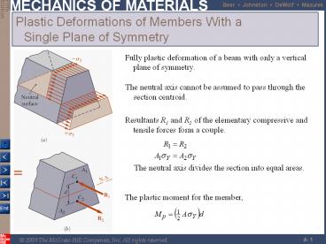
- Fully plastic deformation of a beam with only a
vertical plane of symmetry.
- The neutral axis cannot be assumed to pass
through the section centroid.
2
Residual Stresses
- Plastic zones develop in a member made of an
elastoplastic material if the bending moment is
large enough.
- Since the linear relation between normal stress
and strain applies at all points during the
unloading phase, it may be handled by assuming
the member to be fully elastic.
- Residual stresses are obtained by applying the
principle of superposition to combine the
stresses due to loading with a moment M
(elastoplastic deformation) and unloading with a
moment -M (elastic deformation).
- The final value of stress at a point will not, in
general, be zero.
3
Example 4.05, 4.06
A member of uniform rectangular cross section is
subjected to a bending moment M 36.8 kN-m. The
member is made of an elastoplastic material with
a yield strength of 240 MPa and a modulus of
elasticity of 200 GPa. Determine (a) the
thickness of the elastic core, (b) the radius of
curvature of the neutral surface. After the
loading has been reduced back to zero, determine
(c) the distribution of residual stresses, (d)
radius of curvature.
4
Example 4.05, 4.06
5
Example 4.05, 4.06
6
Eccentric Axial Loading in a Plane of Symmetry
- Validity requires stresses below proportional
limit, deformations have negligible effect on
geometry, and stresses not evaluated near points
of load application.
7
Example 4.07
- SOLUTION
- Find the equivalent centric load and bending
moment
- Superpose the uniform stress due to the centric
load and the linear stress due to the bending
moment.
- Evaluate the maximum tensile and compressive
stresses at the inner and outer edges,
respectively, of the superposed stress
distribution.
An open-link chain is obtained by bending
low-carbon steel rods into the shape shown. For
700 N load, determine (a) maximum tensile and
compressive stresses, (b) distance between
section centroid and neutral axis
- Find the neutral axis by determining the location
where the normal stress is zero.
8
Example 4.07
- Normal stress due to a centric load
- Equivalent centric load and bending moment
- Normal stress due to bending moment
9
Example 4.07
- Maximum tensile and compressive stresses
- Neutral axis location
10
Sample Problem 4.8
The largest allowable stresses for the cast iron
link are 30 MPa in tension and 120 MPa in
compression. Determine the largest force P which
can be applied to the link.
- SOLUTION
- Determine equivalent centric load and bending
moment.
- Superpose the stress due to a centric load and
the stress due to bending.
- Evaluate the critical loads for the allowable
tensile and compressive stresses.
From Sample Problem 4.2,
- The largest allowable load is the smallest of the
two critical loads.
11
Sample Problem 4.8
12
Unsymmetric Bending
- Analysis of pure bending has been limited to
members subjected to bending couples acting in a
plane of symmetry.
- Members remain symmetric and bend in the plane of
symmetry.
- The neutral axis of the cross section coincides
with the axis of the couple.
- Will now consider situations in which the bending
couples do not act in a plane of symmetry.
- Cannot assume that the member will bend in the
plane of the couples.
- In general, the neutral axis of the section will
not coincide with the axis of the couple.
13
Unsymmetric Bending
Wish to determine the conditions under which the
neutral axis of a cross section of arbitrary
shape coincides with the axis of the couple as
shown.
14
Unsymmetric Bending
Superposition is applied to determine stresses in
the most general case of unsymmetric bending.
15
Example 4.08
A 180 Nm couple is applied to a rectangular
wooden beam in a plane forming an angle of 30
deg. with the vertical. Determine (a) the
maximum stress in the beam, (b) the angle that
the neutral axis forms with the horizontal plane.
16
Example 4.08
- Resolve the couple vector into components and
calculate the corresponding maximum stresses.
- The largest tensile stress due to the combined
loading occurs at A.
17
Example 4.08
- Determine the angle of the neutral axis.
18
General Case of Eccentric Axial Loading
- Consider a straight member subject to equal and
opposite eccentric forces.
Recommended
CrystalGraphics Presentations


