
Engine Parts - PowerPoint PPT Presentation
1 / 29
Title:
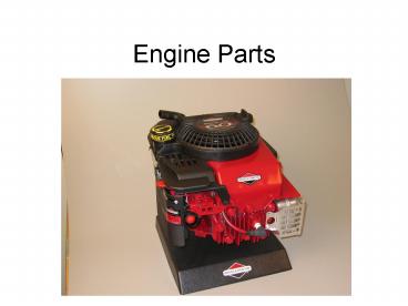
Engine Parts
Description:
Uses Magnetic Induction System From Flywheel Magnets To Produce Electrical Charge Block Contains the Cylinder Valve Stem Guides Valve Ports Sump (holds oil) ... – PowerPoint PPT presentation
Number of Views:98
Avg rating:3.0/5.0
Title: Engine Parts
1
Engine Parts
2
Air Filter
- Pre Filter in the cover
- Should be free of grit, oil gas
- Filter
- Cardboard
- Change every 25 operating hours or season
- Cannot be oil or gas soaked
3
Blower Housing
- Contains the pull start
- Covers the flywheel
- Protects against muffler burns
- Most common place to find a model number
- Housing Directs Air From Flywheel Fan To Cool
Different Areas Of Engine, Especially Around
Cylinder Portion Of Crankcase - Be Sure Area Is Free From Dirt And Debris, Which
Would Cause Overheating.
4
Brake Bracket
- Must be set before replacing on the engine
- Check the kill switch connection
5
Carburetor
- Purpose
- To atomize gas
- To give proper mixture to fuel and air
- Choked
- Air is blocked off
- You have a rich fuel mixture
- Why would you do this?
6
Connecting Rod
- The cap is torqued in in. lbs.
- Connects the piston to the crankshaft
7
Flywheel
- Contains Magnet To Induce Ignition Coil At A
Specific Time Due To Location - Contains Fins To Pull In Cooling Air For Cylinder
- Its Mass Carries Momentum To Maintain Engine
Rotation During Exhaust, Intake And Compression
Stroke. - Has Starter Cup Attached
- Used To Transfer Rotation From Rewind To Start
Engine.
8
Fuel Tube
- Heavy corded tube
- Different in 2- and 4- stroke engines
9
GovernorHelps control engine speed and prevents
overheating
Governor Linkage Goes from throttle control on
the carburetor to the governor arm under the
flywheel
Governor Arm Connects the governor linkage to
the internal governor paddle in the engine block.
10
Piston
- Creates Vacuum During Intake
- Causes Air Fuel Mixture To Compress
- Transfers Burn Of Fuel Mixture Into Linear
Movement - Forces Burnt Gases Out Of Cylinder
- Contains Piston Rings
- Seal Against Compression Leakage
- Movement Of Lubricating Oil
11
Rewind Starter Spring
- Goes in the blower housing
- Straighten it to retention it
12
Valves
- Exhaust Valve
- Doorway To Allow Burnt Air-Fuel Mix Out Of
Cylinder. - Must Be Able To Withstand High Temperatures
Intake Valve - Doorway To Allow Fresh Air-
Fuel Mixture Into Cylinder.
13
Armature
- Produces High Voltage Electrical Charge For Spark
Plug - Contains Primary And Secondary Coils Of Wire
Along With A Transistor. - Uses Magnetic Induction System From Flywheel
Magnets To Produce Electrical Charge
14
Block
- Contains the Cylinder
- Valve Stem Guides
- Valve Ports
- Sump (holds oil)
- Cooling Fins
15
Breather
- Contains Reed-Style Type Breather.
- See Discussion Regarding Vacuum At Removal Of Air
Cleaner Back Plate - Breather Functions As A One Way Check Valve.
Allows Crankcase Air To Exit Cylinder During
Power And Intake Stroke, Closes To Prevent Air
From Going Back In During Exhaust And Compression
Stroke
16
Cam and Tappets
- Lobes
- Transfer Motion To Tappets For Opening And
Closing Of Valves. - Height Of Lobes Affect How Long The Valve Is
Open. - Gear has timing mark
Compression Release
Lobe
- Compression Release Mechanism
- Slightly Opens A Valve For Easy Starting.
- Once Engine Has Started, Mechanism Will Move Out
Of The Way For Full Compression
17
Crankshaft
- Converts Linear Motion Into Rotational Motion.
- Attaches To A Device For Producing Work, Example
Mower Blade, Belts, Hydraulic Pump, Etc. - Supported At Both Ends In Cylinder Housing By
Bearings. - Contains An Offset For Connecting Rod.
- Offset Affects The Amount Of Piston Travel In
Bore. (Displacement) - Contains Gear.
- Used To Drive Camshaft.
- ½ Diameter Of Cam Gear For 2-1 Ratio
- Has Timing Mark For Proper Orientation
18
Crankshaft Parts
Counter Weights
PTO
Magneto
Crankpin or Connecting Rod Journal
19
Cylinder
- Structure For Engine
- Contains Cooling Fins For Heat Transfer
- Made From Aluminum
- Some Units May Contain A Cast Iron Sleeve For
Longer Wear
20
Head
- Incorporates Cooling Fins
- Used To Dissipate Heat
21
Head Bolt
- Always tighten in a star pattern
- If there are any longer, they go around the
muffler
22
Fuel Tank
- Older models are metal
- Carb sat on top
- There was a pump
- Newer models are plastic
- Fuel filter inside of the tank of many
- Gravity feed now
23
Intake Manifold Tube
- Carries Air Fuel Mixture From Carburetor To
Intake Manifold - Constructed Of A Polymer Material To Resist Heat
24
Muffler
- Reduces Engine Noise
- Used To Direct Out Going Hot Gases
25
Oil Slinger/Governor Gear
- Paddles On Outside Of Gear Serve As An Oil
Slinger. - As Assembly Spins, Paddles Will Splash Oil To
Various Areas Within The Engine. - Contains Governor Assembly
26
Sump Cover
- Contains Surface For Crankshaft To Ride On
- Is The Reservoir To Hold Engine Oil
- Contains Governor Assembly
27
Starter Cup
- Cup Provides The Interface Between The Rewind
Assembly And The Crankshaft
28
Valve Spring
- They look the same
- If one is stronger it belongs on exhaust
- Mark to make sure they get back on valve they
come off
29
Valve Spring Retainers
School Engine Retainer
Recommended
CrystalGraphics Presentations


