
Combinational Circuit - PowerPoint PPT Presentation
Title:
Combinational Circuit
Description:
Combinational Circuit Arithmetic Circuit Parallel Adder Example: 4-bit adder Combinational Circuit Arithmetic Circuit Usage: Poling system (for 6 person) Use ... – PowerPoint PPT presentation
Number of Views:102
Avg rating:3.0/5.0
Title: Combinational Circuit
1
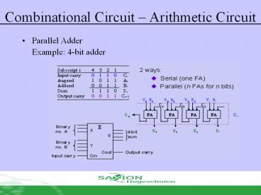
Combinational Circuit Arithmetic Circuit
- Parallel Adder
- Example 4-bit adder
2
Combinational Circuit Arithmetic Circuit
- Usage Poling system (for 6 person)
- Use full adder and parallel adder 4-bit (binary)
- Each full adder can add 3 polls
3
Combinational Gates Arithmetic Circuit
- Comparator
- Magnitude comparator compare two value A and B
to ensure if AgtB, AB or AltB - Classical method need 22n line in TT
- Explore dissimilarity
- How we compare two 4-bit value A(a3 a2 a1 a0) and
B(b3 b2 b1 b0) - If (a3gtb3) therefore AgtB
- If (a3ltb3) therefore AltB
- If (a3b3) therefore AB and so on..
4
Combinational Gates Arithmetic Circuit
A3B3
- A3
x3
A3 B3
B3
A3B3 x3A2B2 x3x2A1B1 x3x2x1A0B0
A2
x2
B2
(AltB)
A1
x1
A3B3 x3A2B2 x3x2A1B1 x3x2x1A0B0
B1
A0
x0
(AgtB)
B0
(AB)
x3x2x1x0
5
Combinational Circuit - Arithmetic Circuit
- Comparator
6
Combinational Circuit MSI Circuit
- There are four useful MSI circuit
- Decoder
- Demultiplexer
- Encoder
- Multiplexer
- Block Diagram
7
Combinational Circuit MSI Circuit
- DECODER
- Codes used for representing entity, e.g. your
name is a code which represent yourself (entity) - This code can be identified (or decoded) using a
decoder Provide code, identify entity - Change binary information from n input line
(maximum value for) 2n output line - Is known as line decoder n to m, or nm or nxm
decoder (mlt2n) - Might be used to generate 2n (or less) minterm
for n input variable
8
Combinational Circuit MSI Circuit
- DECODER
- Example if code 00, 0, 10, 11is used to identify
four bulbs, therefore we need 2-bit decoder - This is 2x4 decoder which select output line
based on the given 2 bit. - Truth table
9
Combinational Circuit MSI Circuit
- DECODER
- From the truth table, decoder circuit 2x4 is
- Notes each output in 2 variable minterm
expression (XY, XY, XY, XY)
10
Combinational Circuit MSI Circuit
- DECODER
- Design of 3x8 decoder
- Usage? Conversion from binary to octal
11
Combinational Circuit MSI Circuit
- DECODER
- In general for n-bit code, decoder suppose to
select up to 2n line
12
Combinational Circuit MSI Circuit
- DECODER Function execution
- Example Full Adder
13
Combinational Circuit MSI Circuit
- DECODER with Enable
- Most decoder has an enable signal, therefore it
only active when enable, E1 - Truth table
14
Combinational Circuit MSI Circuit
- DECODER with Enable
- In MSI, enable signal for decoder is zero enable,
E, therefore this device only active when
enable E0
15
Combinational Circuit MSI Circuit
- LARGE DECODER
- Large decoder can be built using small size
decoder - E.g. 38 decoder can be built using 24 (with 1
enable) as the following
16
Combinational Circuit MSI Circuit
- LARGE DECODER
- E.g. 416 decoder can be built using two 38
decoder (with 1 enable) as the following. - How can you build 416 decoder by using 24
decoder with enable?
17
Combinational Circuit MSI Circuit
- ENCODER
- Encoder is the inversion of decoder.
- Several sets of input line, select one, it
produce similar code for selected line - Consist of 2n (or less) input line and n output
line - Created from OR gate
- Example
18
Combinational Circuit MSI Circuit
- Truth table
Recommended
CrystalGraphics Presentations


