
1Origin and nature of nuclear radiation - PowerPoint PPT Presentation
1 / 87
Title:
1Origin and nature of nuclear radiation
Description:
1 Origin and nature of nuclear radiation Properties of , and radiations (3) Properties of , and radiations (4) Radiation Detectors Photographic Film ... – PowerPoint PPT presentation
Number of Views:170
Avg rating:3.0/5.0
Title: 1Origin and nature of nuclear radiation
1
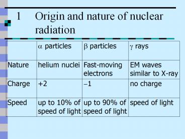
1 Origin and nature of nuclear radiation
2
Properties of ?, ? and ? radiations (2)
0
1/1850
4
Mass (nucleon unit)
No deflection
Large deflection
Very small deflection
Effect of Fields
Very weak (0.01 of ?)
Weak (10 of ?)
Strong
Ionizing power
3
Properties of ?, ? and ? radiations (3)
500 m
5 m
5 cm
Range in air
Never fully absorbed reduced to half by 25 mm
of lead
Stopped by 5 mm of aluminium
Stopped by a sheet of paper
Penetrating power
4
Properties of ?, ? and ? radiations (4)
- Photographic
- film
- Cloud chamber
- GM tube
- Photographic
- film
- Cloud
- chamber
- GM tube
- Photographic
- film
- Ionization
- chamber
- Cloud chamber
- Spark counter
- Thin window
- GM tube
Detectors
No transmutation
Radioactive transmutation
5
5 Deflection in electric magnetic field
a In electric field
?
electric field
? ()
radioactive source
?
? ()
mass of ? gtgt mass of ?
? deflection ? ltlt ?
6
5 Deflection in electric magnetic field
F
b In magnetic field
B
?
I
?
radioactive source
B-field (into paper)
?
Flow of a particles Flow of positive charges
Direction of Current
Flow of b particles Flow of negative charges
Opposite direction of current
7
b In magnetic field
? radiation tracks in a very strong B-field
(Photo credit Lord Blacketts Estate)
8
Radiation Detectors
- Photographic Film
- To detect ?, ? and ? radiations
- Spark counter
- To detect ?-particles
- Ionization Chamber
- To detect ? -particles
- Cloud Chamber
- To detect ? and ? particles
- Geiger-Müller Tube
- To detect ?, ? and ? radiations
9
Photographic Film
- The photographic film has been blackened by
radioactivity except in the shadow of the key.
10
Spark Counter
- The spark counter consists of positively charged
wire mounted under an earthed metal grid. - It produces sparks in the presence of ionized
particles. - It can only be used to detect a-radiation.
11
- When radiation enters the metal can, the gas
inside is ionized. - Under the influence o the electric field,
electrons move towards the anode while the
positive ions move towards the cathode. - As a result, a small ionization current is
produced and is recorded by an electrometer.
12
Note
- 1. When the applied voltage (V) is increased, the
ionization current is larger since more ions and
electrons can reach the electrodes. Until a
certain voltage, all ion-pairs produced reach the
electrodes and a saturated ionization current is
obtained. - 2. The saturated ionization current is increased
with the rate of producing ion-pairs. Therefore,
ionization chamber is suitable for detecting
a-particles and b-particles since their ionizing
powers are relatively strong. But the ionizing
power of g-rays is very weak it cannot be
measured by the ionization chamber.
13
Cloud Chamber (1)
- The diagrams below show a diffusion cloud chamber
and its structure.
14
Cloud Chamber (2)
- The felt ring round the top of the chamber is
soaked with alcohol. - The cooled chamber is full of alcohol vapour.
- A weak radioactive source inside the chamber
emits radiation that produces ions along its
path. - The alcohol vapour which diffuses downwards from
the top condenses around the ions. - The resulting tiny alcohol drops show up as a
track in the bright light
15
Cloud Chamber Tracks (1)
a radiation Having a strong ionizing power, the
heavy ? particles give straight and thick tracks
of about the same length.
16
Tracks of ? rays can hardly be seen.
b radiation They are twisted because the
particles are small in mass and bounce off from
air molecules on collision.
17
Cloud Chamber Tracks (3)
- Under diffusion cloud chamber,
- Alpha source gives thick , straight tracks
- Beta source produces thin, twisted tracks. They
are small in mass and so bounce off from air
molecules on collision. - Gamma source gives scattered, thin tracks. Gamma
rays remove electrons from air molecules. These
electrons behave like beta particles.
18
GM Counter
- When ionizing radiation enters the GM tube, ions
and free electrons are formed. - A flow of charge takes place and causes a pulse
of current. - The pulse of current is amplified and counted
electronically.
19
GM tube
- A GM tube is filled with argon gas and a high
voltage ( 400 V) is applied to the central wire.
20
GM tube
- When radiation enters the tube, it pulls an
electron from an argon atom and produces an
ion-pair. - The resulting electrons rapidly accelerated
towards the anode and cause more ions formed as
they collide with argon gas atoms. - In this way, one electron can lead to the release
of 108 electrons. An avalanche of electrons is
produced. - When the electrons reach the anode, a pulse is
created and can be counted by the GM counter.
21
1 Three types of decay
Alpha decay
22
Example 1
23
No. of throws No. of dice remaining
0 100
1 89
2 71
3 54
4 46
5 37
6 28
7 24
8 20
9 18
10 16
24
- The points plotted do not fall exactly on the
curve. The fluctuations are due to the random
nature of dice throwing. - Radioactive decay is also random in nature
because, like the dice decay the chance of
certain nuclei decaying at a particular time is
random.
25
no. of undecayed nuclei
- Always decreasing.
- Decrease rapidly in the beginning.
- Decreases gently finally.
- Becomes zero after a long time.
Time / s
26
Activity of a radioactive isotope (1)
- Let N(t) be the number of radioactive nuclei in a
sample at time t.
The - sign indicates that N(t) decreases with
time
- The decay rate is directly proportional to N(t).
The SI unit of activity is the becquerel (Bq).
- The constant k is called the decay constant. A
large value - of k corresponds to rapid decay.
27
Activity of a radioactive isotope (2)
From
,
- k can be interpreted as the probability per unit
time that any individual nucleus will decay.
28
no. of undecayed nuclei
- 0 4 s 2000 ? 1000
- 4 8 s 1000 ? 500
- 8 12 s 500 ? 250
- 12 16 s 250 ? 125
- Half life 4 s
- It takes 4 s for half to decay
Time / s
29
Half life t1/2
Half-life t½
30
Half-life (1)
- The graph shows the number of remaining nuclei
N(t) as a function of time.
31
Half-life (2)
- The half-life t1/2 is the time required for the
number of radioactive nuclei to decrease to
one-half the original number No.
- At t t1/2, N(t) No/2, obtaining
- Taking logarithms to base e, gives
32
Cloud Chamber Tracks (2)
33
Rate of decay
- undecayed nucleus
decayed nucleus
34
Radiation hazard
- Ionizing effect can destroy or damage living
cells. - Radioactive gas and dust cannot be removed once
taken in. - Gamma rays are dangerous due to strong
penetrating power
35
Background radiation
Cosmic rays 12
Radioactive material in rocks and soil 15
Radioactive gases 40
Living bodies, and food and drinks 15
Medical practice 17
Nuclear discharge 1
36
Hazards due to sealed and unsealed sources (1)
- Hazards due to sealed sources
- a-particles usually do not present any external
radiation hazard because they are unable to
penetrate to dead layer of skin. But, extremely
precautions must be taken to prevent a-emitters
from getting into the body. - ß-particles never constitute a whole-body
external radiation hazard due to their short
range in tissue. - ?-rays have very high penetrating power and
require greater care to avoid receiving excess
dosage.
37
Hazards due to sealed and unsealed sources (2)
- Hazards due to unsealed sources
- Unsealed sources usually constitute some kind of
internal hazard. This is the absorption and
retention of radionuclides into specific organs
of the body through intake of the materials
present in air and in water. - The radionuclides may be rapidly absorbed by the
organs causing damage to these organs.
38
Radioactive doses
- The radiation emitted transfers energy to the
organs and causes damage. - The level of damage depends on
- 1. energy absorbed by the body
- 2. type of radiation
- 3. the parts of human body
39
- Effective dose
- Absorbed dose x Radiation weighting factor x
tissue weighting factor
40
Handling precautions
- The weak sources used at school should always by
lifted with forceps. - The sources should never by held near the eyes.
- The source should be kept in their boxes (lead
container) when not in use. - Take great care not to drop the sources when
handling them. - Carefully plan the experiments to minimize the
time the source is used.
41
Uses of radioisotopes
- Medical uses
- Treatment of body cancer
- Investigation of Thyroid Gland (???)
- Radon-222 (a emitted)
- Iodine-131 (g emitted)
42
Industrial uses
Application Type of radiation Half life
Thickness gauge a / b / g Long / short
Checking oil leakage a / b / g Long / short
Smoke detector a / b / g Long / short
43
Archaeological Use (Carbon-14 dating)
- Carbon-14 exists due to formation by bombardment
of nitrogen-14 in atmosphere by neutrons ejected
from nuclei by cosmic rays ( ) and this forms
radioactive carbon dioxide. - Living plants or trees absorb and give out carbon
dioxide, so the percentage of C-14 in their
tissue remains unchanged. - After death, no fresh CO2 taken in.
- C-14 starts to decay with a half-life of 5.7 ?
103 years. - By measuring the activity of C-14 ( ), the age
of carbon containing material (e.g. wood, linen,
charcoal) can be estimated.
44
- End of this chapter
45
Alpha-Scattering Experiment (1)
- A beam of ?-particles was directed at a thin
sheet of gold-foil and the scattered ?-particles
were detected using a small zinc sulphide screen
viewed through a microscope in a vacuum chamber.
46
Alpha-scattering Experiment (2)
- From the experiment it was found that
- most of the ?-particles passed through the foil
unaffected,
- a few were deflected at very large angles,
- some were nearly reflected back in the direction
from which they had come.
47
Rutherfords atomic model
- Rutherfords assumptions
- All the atoms positive charge is concentrated in
a relatively small volume, called the nucleus of
the atom
- The electrons surround the nucleus at relatively
large distance. - Most of the atoms mass is concentrated in its
nucleus.
48
Difficulties of Rutherfords model
- The Rutherford model was unable to explain why
atoms emit line spectra. The main difficulties
are - It predicts that light of a continuous range of
frequencies will be emitted - It predicts atoms are unstableelectrons should
quickly spiral into the nucleus.
49
Mass and Energy
- The mass-energy relationship
- Einstein showed that mass and energy are
equivalent. - E mc2
- Mass defect
- The difference between the mass of an atom and
the mass of its particles taken separately is
called the mass defect (?m). - ?m Zmp Nmn- Mnucleus
- The mass defect is small compared with the total
mass of the atom.
50
Unified Atomic Mass Unit
- The unified atomic mass unit (u) is defined as
one twelfth of the mass of the carbon atom which
contains six protons, six neutrons and six
electrons. - 1 u 1.660566 10-27 kg
- Energy equivalence of mass
- 1 u 931.5 MeV
- It is a useful quantity to calculate the energy
change in nuclear transformations.
51
Binding Energy (1)
- The energy required to just take all the nucleons
apart so that they are completely separated is
called the binding energy of the nucleus.
52
Binding Energy (2)
- From Einsteins mass-energy relation, the total
mass of all separated nucleons is greater than
that of the nucleus, in which they are together.
The difference in mass is a measure of the
binding energy. - According to relativity theory,
- total binding energy ?mc2
- where ?m is the mass defect of the nucleus.
53
Binding Energy (3)
- Binding energy of Helium
?m 4.0330 u - 4.0026 u
0.0304 u
? E 28.3 MeV
Binding energy per nucleon 7.08 MeV per nucleon
54
Binding Energy (4)
- The values of the binding energy varies from one
nuclear structure to another. - The greater the binding energy per nucleon, the
more stable the nuclei.
55
Binding Energy Curve (1)
- The graph shows the variation of the binding
energy per nucleon among the elements.
Fission
Fusion
56
Binding energy Curve (2)
- The important features of the binding energy
curve - Maximum binding energy per nucleon is at about
nucleon number A 50. Maximum binding energy per
nucleon corresponds to the most stable nuclei. - Either side of maximum binding energy per nucleon
are less stable.
57
Binding Energy Curve (3)
- When light nuclei are joined together, the
binding energy per nucleon is also increased. So
energy is released when light nuclei are fused
together. - When a big nucleus disintegrates, the binding
energy per nucleon increases and energy is
released. So fission or radioactive decay both
lead to an increase of binding energy per nucleon
and hence to release energy as KE of the product.
58
Principles of Nuclear Fission (1)
- Nuclear fission is a decay process in which an
unstable nucleus splits into two fragments of
comparable mass.
- Two typical nuclear fission reactions are
59
Principles of Nuclear Fission (2)
- Further investigations showed that
- several neutrons are released with the fission
fragments, - many fission products are possible when U-235 is
bombarded with neutrons, - the products themselves are radioactive,
- slow neutrons are more effective in fissioning
U-235 than fast neutrons, - energy is released on much greater scale than is
released from chemical reaction.
60
Chain Reactions
http//www.smartown.com/sp2000/energy_planet/en/tr
ad/fission.html
- Fission of uranium nucleus, triggered by neutron
bombardment, released other neutrons that can
trigger more fission. Chain reaction is said to
occur.
61
Nuclear Power Plant
- A power plant with cooling tower
62
Nuclear Reactor (1)
http//www.ae4rv.com/games/nuke.htm
- The schematic diagram of a nuclear reactor is
shown below
63
Nuclear Reactor (2)
- Enriched uranium is used as the fuel.
- The fuel is in the form of rods enclosed in metal
containers. - A moderator is used to slow down fission
neutrons. - Control rods are used to absorb neutrons to
maintain a steady rate of fissioning. - A coolant is pumped through the channels in the
moderator to remove heat energy to a heat
exchanger.
64
Processes inside the Nuclear Reactor
- Each fission of U-235 nucleus produces fission
fragments including neutrons. The fission
fragments carry away most of the KE and transfer
the KE to other atoms that they collide with. So
the fuel pin get very hot. - The fission neutrons enter the moderator and
collide with moderator atoms, transferring KE to
these atoms. So the neutrons slow down until the
average KE of a neutron is about the same as that
of a moderator atom. - Slow neutron re-enter the fuel pins and cause
further fission of U-235 nuclei.
65
Important features in the design of a nuclear
reactor (1)
- The critical mass of fuel required
- The critical mass of fuel is the minimum mass
capable of producing a self-sustaining chain
reaction. - The fission neutrons could be absorbed by the
U-238 nuclei without producing further fission. - The fission neutron could escape from the
isolated block of uranium block without causing
further fission.
66
Important features in the design of a nuclear
reactor (2)
- The choice of the moderator
- The atoms of an ideal moderator should have the
same mass as a neutron. So a neutron colliding
elastically with a moderator atom would lose
almost all its KE to the moderator atom. - In practice, graphite or heavy water (D2O) is
chosen as the moderator. - The moderator atoms should not absorb neutrons
but should scatter them instead.
67
Important features in the design of a nuclear
reactor (3)
- The choice of control rods
- The control rods absorb rather than scatter
neutrons. - Boron and cadmium are very suitable elements for
control rods. - Control rods are operated automatically.
68
Important features in the design of a nuclear
reactor (4)
- Coolants should ideally have the following
properties - The coolant must have high heat transfer
coefficient. - The coolant must flow easily.
- The coolant must not be corrosive.
- Coolant atoms may become radioactive when they
pass through the core of the reactor. So the
coolant must have low induced radioactivity. - The coolant must be in a sealed circuit.
69
Important features in the design of a nuclear
reactor (5)
- The treatment of waste
- The fuel rods are stored in containers in cooling
ponds until their activity has decreased and they
are cooler. - The spent fuel is removed from the cans by remote
control. The fuel is then reprocessed to recover
unused fuel. - the unwanted material is then stored in sealed
containers for many years until the activity has
fallen to an insignificant.
70
Nuclear Fusion
- Fusion is combining the nuclei of light elements
to form a heavier element. This is a nuclear
reaction and results in the release of large
amounts of energy! - Energy is released due to the increase in binding
energy of the product of the reaction. - In a fusion reaction, the total mass of the
resultant nuclei is slightly less than the total
mass of the original particles.
71
Example of Nuclear Fusion
- An example of nuclear fusion can be seen in the
Deuterium-Tritium Fusion Reaction.
72
Conditions for a Fusion Reaction (1)
- Temperature
- Fusion reactions occur at a sufficient rate only
at very high temperature. Over 108 oC is needed
for the Deuterium-Tritium reaction. - Density
- The density of fuel ions must be sufficiently
large for fusion reactions to take place at the
required rate. The fusion power generated is
reduced if the fuel is diluted by impurity atoms
or by the accumulation of Helium ash from the
fusion reaction. - As fuel ions are burnt in the fusion process they
must be replaced by new fuel and the Helium ash
must be removed.
73
Conditions for a Fusion Reaction (2)
- Confinement
- The hot plasma must be well isolated away from
material surfaces in order to avoid cooling the
plasma and releasing impurities that would
contaminate and further cool the plasma. - In the Tokamak system, the plasma is isolated by
magnetic fields.
74
Advantages of Nuclear Fusion
- Abundant fuel supply
- No risk of a nuclear accident
- No air pollution
- No high-level nuclear waste
- No generation of weapons material
75
Nuclear Waste
Some waste is stored on asphalt pads in drums.
76
Storage Tanks for Nuclear Waste
- These storage tanks were constructed to store
liquid, high-level waste. After construction was
completed, the earth was replaced to bury the
tanks underground.
77
Nuclear Stability (1)
- The Segrè chart below shows neutron number and
proton number for stable nuclides.
- For low mass numbers, N?Z.
- The ratio N/Z increases with A.
- Points to the right of the stability region
represents nuclides that have too many protons
relative to neutrons. - To the left of the stability region are nuclides
with too many neutrons relative to protons.
78
Nuclear Stability (2)
79
Nuclear Stability (3)
80
Deflection of a, ß and ? rays in electric and
magnetic fields (1)
81
Deflection of a, ß and ? rays in electric and
magnetic fields (2)
- Under the effect of electric field or magnetic
field, (in the direction of going into the
paper) - a-ray shows small deflection in an upward
direction - ß-ray shows a larger deflection than that of
alpha ray, and in a downward direction - ?-ray shows no deflection.
82
Penetrating Power
- The diagram below shows the apparatus used to
deduce the penetrating abilities of a, ß and ?
radiations.
83
Moderator
http//www.npp.hu/mukodes/lancreakcio-e.htm
- Use materials that slow the neutrons down to such
low energies at which the probability of causing
a fission is significantly higher. These neutron
slowing down materials are the so called
moderators.
84
Control rods
- Reactor core glowing at full licensed power
- reactor core at the bottom of a 5 m deep tank of
very pure water
85
Heating of Plasma (1)
- Ohmic Heating and Current Drive
- Currents up to 7 million amperes (7MA) flow in
the plasma and deposit a few mega-watts of
heating power. - Neutral Beam Heating
- Beams of deuterium or tritium ions, accelerated
by a potential of 140,000 volts, are injected
into the plasma. - Radio-Frequency Heating
- The plasma ions and electrons rotate around in
the magnetic field lines of the tokamak. Energy
is given to the plasma at the precise location
where the radio waves resonate with the ion
rotation.
86
Heating of Plasma (2)
- Current Driven by Microwaves
- 10 MW of microwaves at 3.7 GHz accelerate the
plasma electrons to generate a plasma current of
up to 3MA. - Self Heating of Plasma
- The helium nuclei (alpha-particles) produced when
deuterium and tritium fuse remain within the
plasma's magnetic trap. Their energy continues to
heat the plasma to keep the fusion reaction
going.
87
JET Tokamak
- During operation large forces are produced due to
interactions between the currents and magnetic
fields. These forces are constrained by the
mechanical structure which encloses the central
components of the machine.
Recommended
CrystalGraphics Presentations


