
Electromagnetic Induction - PowerPoint PPT Presentation
1 / 35
Title: Electromagnetic Induction
1
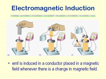
Electromagnetic Induction
- emf is induced in a conductor placed in a
magnetic field whenever there is a change in
magnetic field.
2
Moving Conductor in a Magnetic Field
- Consider a straight conductor moving with a
uniform velocity, v, in a stationary magnetic
field. - The free charges in the conductor experience a
force which will push them to one end of the
conductor. - An electric field is built up due to the electron
accumulation. - An e.m.f. is generated across the conductor such
that - E Blv.
3
Induced Current in Wire Loop
- An induced current passes around the circuit when
the rod is moved along the rail. - The induced current in the rod causes a force F
IlB, which opposes the motion.
- Work done by the applied force to keep the rod
moving is
- Electrical energy is produced from the work
done such that
E E I?t W
?E Blv
4
Lenzs Law
- The direction of the induced current is always so
as to oppose the change which causes the current.
5
Magnetic Flux
- The magnetic flux is a measure of the number of
magnetic field lines linking a surface of
cross-sectional area A.
- The magnetic flux through a small surface is the
product of the magnetic flux density normal to
the surface and the area of the surface.
Unit weber (Wb)
6
Faradays Law of Electromagnetic Induction
- The induced e.m.f. in a circuit is equal to the
rate of change of magnetic flux linkage through
the circuit.
The - sign indicates that the induced e.m.f.
acts to oppose the change.
http//physicsstudio.indstate.edu/java/physlets/ja
va/indcur/index.html
7
Induced Currents Caused by Changes in Magnetic
Flux
- The magnetic flux (number of field lines passing
through the coil) changes as the magnet moves
towards or away from the coil.
http//micro.magnet.fsu.edu/electromag/java/lenzla
w/index.html
8
Faraday Disk Dynamo
9
Simple a.c. Generator
- According to the Faradays law of electromagnetic
induction,
http//www.walter-fendt.de/ph11e/generator_e.htm
10
Simple d.c. Generator
11
Eddy Current
- An eddy current is a swirling current set up in a
conductor in response to a changing magnetic
field.
- Production of eddy currents in a rotating wheel
12
Applications of Eddy Current (1)
- Metal Detector
13
Applications of Eddy Current (2)
- Eddy current levitator
- Smooth braking device
- Damping of a vibrating system
14
Back emf in Motors
- When an electric motor is running, its armature
windings are cutting through the magnetic field
of the stator. Thus the motor is acting also as a
generator. - According to Lenz's Law, the induced voltage in
the armature will oppose the applied voltage in
the stator. - This induced voltage is called back emf.
15
Back emf and Power
Multiplying by I, then
- So the mechanical power developed in motor
16
Variation of current as a motor is started
Larger load
Zero load
- As the coil rotates, the angular speed as well as
the back emf increases and the current decreases
until the motor reaches a steady state.
17
The need for a starting resistance in a motor
- When the motor is first switched on, ? 0.
- The initial current, IoV/R, very large if R is
small. - When the motor is running, the back emf
increases, so the current decrease to its working
value. - To prevent the armature burning out under a high
starting current, it is placed in series with a
rheostat, whose resistance is decreases as the
motor gathers speed.
18
Variation of current with the steady angular
speed of the coil in a motor
- The maximum speed of the motor occurs when the
current in the motor is zero.
19
Variation of output power with the steady angular
speed of the coil in a motor
- The output power is maximum when the back emf is
½ V.
20
Transformer
- A transformer is a device for stepping up or down
an alternating voltage. - For an ideal transformer,
- (i.e. zero resistance and no flux leakage)
21
Transformer Energy Losses
- Heat Losses
- Copper losses - Heating effect occurs in the
copper coils by the current in them. - Eddy current losses - Induced eddy currents flow
in the soft iron core due to the flux changes in
the metal. - Magnetic Losses
- Hysteresis losses - The core dissipates energy on
repeated magnetization. - Flux leakage - Some magnetic flux does not pass
through the iron core.
22
Designing a transformer to reduce power losses
- Thick copper wire of low resistance is used to
reduce the heating effect (I2R). - The iron core is laminated, the high resistance
between the laminations reduces the eddy currents
as well as the heat produced. - The core is made of very soft iron, which is very
easily magnetized and demagnetized. - The core is designed for maximum linkage, common
method is to wind the secondary coil on the top
of the primary coil and the iron core must always
form a closed loop of iron.
23
Transmission of Electrical Energy
- Wires must have a low resistance to reduce power
loss. - Electrical power must be transmitted at low
currents to reduce power loss. - To carry the same power at low current we must
use a high voltage. - To step up to a high voltage at the beginning of
a transmission line and to step down to a low
voltage again at the end we need transformers.
24
Direct Current Transmission
- Advantages
- a.c. produces alternating magnetic field which
induces current in nearby wires and so reduce
transmitted power this is absent in d.c. - It is possible to transmit d.c. at a higher
average voltage than a.c. since for d.c., the rms
value equals the peak and breakdown of
insulation or of air is determined by the peak
voltage. - Disadvantage
- Changing voltage with d.c. is more difficult and
expensive.
25
Self Induction
- When a changing current passes through a coil or
solenoid, a changing magnetic flux is produced
inside the coil, and this in turn induces an emf.
- This emf opposes the change in flux and is called
self-induced emf. - The self-induced emf will be against the current
if it is increasing. - This phenomenon is called self-induction.
26
Definitions of Self-inductance (1)
- Definition used to find L
The magnetic flux linkage in a coil ? the current
flowing through the coil.
Where L is the constant of proportionality for
the coil. L is numerically equal to the flux
linkage of a circuit when unit current flows
through it.
Unit Wb A-1 or H (henry)
27
Definitions of Self-inductance (2)
- Definition that describes the behaviour of an
inductor in a circuit
L is numerically equal to the emf induced in the
circuit when the current changes at the rate of
1 A in each second.
28
Inductors
- Coils designed to produce large self-induced emfs
are called inductors (or chokes). - In d.c. circuit, they are used to slow the growth
of current. - Circuit symbol
or
29
Inductance of a Solenoid
- Since the magnetic flux density due to a solenoid
is
- By the Faradays law of electromagnetic induction,
30
Energy Stored in an Inductor
- The work done against the back emf in bringing
the current from zero to a steady value Io is
31
Current growth in an RL circuit
- At t 0, the current is zero.
- So
- As the current grows, the p.d. across the
resistor increases. So the self-induced emf (? -
IR) falls hence the rate of growth of current
falls.
- As t??
32
Decay of Current through an Inductor
- Time constant for RL circuit
- The time constant is the time for current to
decrease to 1/e of its original value.
- The time constant is a measure of how quickly the
current grows or decays.
33
emf across contacts at break
- To prevent sparking at the contacts of a switch
in an inductive circuit, a capacitor is often
connected across the switch.
The energy originally stored in the magnetic
field of the coil is now stored in the electric
field of the capacitor.
34
Switch Design
- An example of using a protection diode with a
relay coil.
- A blocking diode parallel to the inductive coil
is used to reduce the high back emf present
across the contacts when the switch opens.
35
Non-Inductive Coil
- To minimize the self-inductance, the coils of
resistance boxes are wound so as to set up
extremely small magnetic fields. - The wire is double-back on itself. Each part of
the coil is then travelled by the same current in
opposite directions and so the resultant magnetic
field is negligible.