
Matching Geometric Models via Alignment - PowerPoint PPT Presentation
Title:
Matching Geometric Models via Alignment
Description:
Matching Geometric Models via Alignment Alignment is the most common paradigm for matching 3D models to either 2D or 3D data. The steps are: 1. hypothesize a ... – PowerPoint PPT presentation
Number of Views:62
Avg rating:3.0/5.0
Title: Matching Geometric Models via Alignment
1
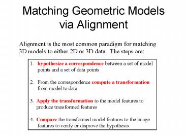
Matching Geometric Modelsvia Alignment
Alignment is the most common paradigm for
matching 3D models to either 2D or 3D data. The
steps are
1. hypothesize a correspondence between a set
of model points and a set of data
points 2. From the correspondence compute a
transformation from model to data 3.
Apply the transformation to the model features
to produce transformed features 4. Compare
the transformed model features to the image
features to verify or disprove the hypothesis
2
2D-3D Alignment
- single 2D images of the objects
- 3D object models
- - full 3D models, such as GC or SEV
- - view class models representing
characteristic - views of the objects
3
View Classes and Viewing Sphere
- The space of view points can be
- partitioned into a finite set of
- characteristic views.
- Each view class represents a set of
- view points that have something
- in common, such as
- 1. same surfaces are visible
- 2. same line segments are visible
- 3. relational distance between pairs of them
is small
V
v
4
3 View Classes of a Cube
1 surface 2 surfaces 3
surfaces
5
RIO Relational Indexing for Object Recognition
- RIO worked with industrial parts that could have
- - planar surfaces
- - cylindrical surfaces
- - threads
6
Object Representation in RIO
- 3D objects are represented by a 3D mesh and set
of 2D view classes. - Each view class is represented by an attributed
graph whose - nodes are features and whose attributed edges
are relationships. - For purposes of indexing, attributed graphs are
stored as - sets of 2-graphs, graphs with 2 nodes and 2
relationships.
share an arc
coaxial arc cluster
ellipse
7
RIO Features
ellipses coaxials
coaxials-multi
parallel lines
junctions triples close
and far L V
Y Z U
8
RIO Relationships
- share one arc
- share one line
- share two lines
- coaxial
- close at extremal points
- bounding box encloses / enclosed by
9
Hexnut Object
What other features and relationships can you
find?
10
Graph and 2-Graph Representations
1 coaxials- multi
encloses
1 1 2 3 2 3
3 2
encloses
2 ellipse
e e e c
encloses
3 parallel lines
coaxial
11
Relational Indexing for Recognition
Preprocessing (off-line) Phase
- for each model view Mi in the database
- encode each 2-graph of Mi to produce an index
- store Mi and associated information in the
indexed - bin of a hash table H
12
Matching (on-line) phase
- Construct a relational (2-graph) description D
for the scene - For each 2-graph G of D
- Select the Mis with high votes as possible
hypotheses - Verify or disprove via alignment, using the 3D
meshes
- encode it, producing an index to access the hash
table H - cast a vote for each Mi in the associated bin
13
The Voting Process
14
Verification
- The matched features of the hypothesized object
are - used to determine its pose. Pose is computed
from - correspondences between 2D and 3D points,
lines, - and circles.
- 2. The 3D mesh of the object is used to project
all its - features onto the image using perspective
projection - and hidden feature removal.
- 3. A verification procedure checks how well the
object - features line up with edges on the image,
using a - Hausdorf distance between expected and
existing edges.
15
Feature Extraction
16
Some Test Scenes
17
Sample Alignments3D to 2D Perspective Projection
18
RIO Verifications
incorrect hypothesis
Recommended
CrystalGraphics Presentations


