
Thermography - Understanding our thermal world - PowerPoint PPT Presentation
1 / 42
Title:
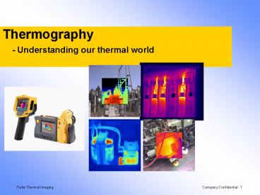
Thermography - Understanding our thermal world
Description:
... or visual image Infrared radiation is emitted by all objects based on their ... 389,601 Electronics $ ... Power Transmission & Distribution ... – PowerPoint PPT presentation
Number of Views:456
Avg rating:3.0/5.0
Title: Thermography - Understanding our thermal world
1
Thermography - Understanding our thermal world
2
Agenda
- Thermography
- What, Why and Where
- Applications
- How a Thermal Imager works
- How Does an Imager Measure Temperature
- Thermography Physics and Heat Transfer
- Resolving detail and capturing a good image
- Additional training support
- Imager hands-on
- Questions?
3
What is Thermography?
- It is the science of seeing temperatures by
measuring the radiation emitted from a given
surface and converting this data to a
corresponding digital, or visual image - Infrared radiation is emitted by all objects
based on their temperature - The amount of radiation increases with
temperature - We are only measuring the surface temperature
4
Why use Thermal Imaging?
- Hot or cold areas, or thermal anomalies, often
are a strong indicator of equipment health. - Allows maintenance personnel to become more
proactive and less reactive. - Thermal Imaging works well to inspect
- Electrical Equipment
- Mechanical Equipment
- Heating/Cooling Equipment
- Building Envelope
- Electronic circuits and boards
- Medical/Health screening
- Other!
5
Temperature Measurements
- Fast, safe and accurate non-contact measurements
can be obtained from objects even if the are - moving or very hot
- difficult to reach
- expensive to shut-down
- dangerous to contact
- contaminated or altered if contacted
6
Downtime is expensive
- Industry Sector Revenue/Hour
- Chemicals 704,101
- Construction and Engineering 389,601
- Electronics 477,366
- Energy 2,817,846
- Food/beverage processing 804,192
- Manufacturing 1,610,654
- Metals/natural resources 580,588
- Pharmaceuticals 1,082,252
- Utilities 643,250
Source Jacksonville Power Authority
7
Power Transmission Distribution applications
8
Substation transformers
Note temperature difference
9
Substation transformers
10
Transformer Cooling
Some cooling tubes appear to be plugged
11
Oil cooled transformer
12
Pad-mount transformers
Look for consistent temperatures across all
elbows
13
Transformers elbows
Look for problems in both internal and external
connections
14
Hot bushing
15
Pole transformer
16
Pole transformer connection
17
Utility Connection
18
Utility connection
19
Electrical panels and circuits
- Overloaded systems or excessive current
- Loose or corroded connections
- Component failures
- Wiring mistakes
- Under-specified components
- Power quality problems like phase unbalance,
overload or harmonic distortion - Insulation failures
Image shown here is Picture-In-Picture (PIP) mode
where center ¼ of image is IR surrounded by ¾
visible
20
Thermography helped distinguish between loose
connection and overloaded circuit
- Courtesy of Snell Infrared
21
IR inspection windows
- IR windows provide faster, safer equipment
inspections - High-voltage Switchgear
- Medium-voltage Switchgear
- Dry-Type Transformers
- Motor Control Centers
- Other areas where Arc Flash Hazard exists
22
Breaker Panel
Two lighting breakers are 35F above ambient
23
In the beginning
- In 1800, Sir William Herschel discovered that by
passing sunlight through a glass prism and
measuring the temperature of the colors, the
temperature increased from the violet to the red
part of the spectrum. - He decided to measure the areas just beyond the
red portion and this was the highest temperature
of all! - He found these calorific rays, which existed
beyond visible light, were reflected, refracted,
absorbed and transmitted just like visible light - These rays were re-named infrared radiation
prefix means below
24
Infrared Radiation
- Infrared radiation is electromagnetic radiation
with wavelengths longer than visible light but
shorter than microwaves - Infrared radiation is radiated heat that cannot
be seen by our eyes but can be sensed by our skin - All objects, whatever their temperature, emit
infrared radiation - The intensity of infrared radiation depends on
the temperature and a surface property termed
emissivity - When an object reaches approximately
644?C(1200?F) visible light is emitted
25
Infrared spectrum
Visible light
Ultra- violet
Gamma- rays
Infrared
µwave
Radio
X-rays
Long-wave 8-14µ
Mid-wave 2-6µ
IR atmospheric transmission bands
26
jumping forward
- Honeywell was a major supplier of military
infrared systems in the 80s but the detectors
required cooling to -340F - Received 12 million of top-secret contracts to
developed a long-wave infrared detector array
technology that required no cooling - First to develop the microbolometer
- Sold large infrared products division in 1989
- Military declassified the use of microbolometer
technology in 1992 - Licensed microbolometer technology to other
manufacturers
27
Microbolometer Technology
- VOx is deposited onto tiny platelets
- Incoming target radiation heats the VOx causing a
change in electrical resistance which is read by
measuring the resulting change in bias current. - Sensors can detect temperature change as slight
as 0.05 C
28
How do we get a picture?
- Each of the thousands of elements, or pixels,
contain an accurate temperature value. The
Imager, through the use of a complex set of
algorithms, assign specific colors that
correspond exactly with the temperature value
found at the specific X Y coordinate.
- Some cameras save a simple picture which does not
actually contain any measurements. - Fully radiometric cameras store the actual
temperature measurements which can be brought
into a PC later for analysis.
29
How does it work?
- 19,200 detectors or more are fabricated into a
two-dimensional array called a Focal Plane Array
(FPA) - Each individual detector measures the incoming
radiation and converts this data to a thermogram,
or visual image, which we use for detailed
temperature analysis and documentation.
Its like having Thousands of infrared
thermometers in one instrument
30
Distance to Spot Ratio DS
Distance to Spot Ratio is distance from
instrument to the object compared to the size of
the the spot being measured
1 ft.
30 feet
301
31
Focal Plane Array Resolution
- 160 x 120 or 320 x 240 FPAs are most common
- 160 x 120 has 19,200 elements
- 320 x 240 has 76,800 elements
- Advantages and Disadvantages
- 320x240 arrays have four times as many pixels
- All other things being equal the imager with a
320 x 240 FPA will have four times finer detail - Imagers made with 160 by 120 arrays are usually
less expensive - Many parameters determine image quality other
than array size, or pixel count - Electronics
- Optics/Lenses
- Thermal sensitivity (NETD)
32
Selecting the Detector Array SizeDepends on the
Application
- Target size needed in a single image
- Target distance
- Spatial resolution (spot size)
- Temperature measurement accuracy
- Budget
33
Temperature
- Temperature is what we commonly think of as hot
or cold - It is a measure of the molecular vibration in an
object relative to the molecular vibration in
other objects - Molecules vibrate faster in warmer objects and
slower in cooler objects - Faster moving objects transfer their energy when
they come into contact with slower moving objects
until they reach equilibrium - Fahrenheit and Celsius are the most commonly used
temperature scales - They use the freezing and boiling points of water
as reference points
34
1st Law of Thermodynamics
- Defines the conservation of energy
- - Energy is neither created nor destroyed, just
converted from one form to another. In a closed
system, the energy entering the system equals
the energy leaving the system. - Example Hydro-electric power plant converts
kinetic energy (water flow) into mechanical
(turbines) and finally to electrical energy
(generators).
35
Heat Energy
- Energy exists in many forms
- Mechanical
- Electrical
- Chemical
- Nuclear
- Thermal (heat)
- It is energy that is absorbed or released as an
object changes temperature - Measured in Btus, 1 Btu heat energy needed to
raise temp of one pound of water one degree F
36
Heat Transfer
- Heat energy always moves from warmer to colder
areas - This allows us to see moisture or missing
insulation - Problems in electrical and mechanical
applications are probably much hotter or worse
than it appears on the surface! - Heat transfer can be
- Steady state heat flow is constant with time
- Transient temperature is constantly and
significantly changing
37
Three Modes of Heat Transfer
- Radiation is the transmission of electromagnetic
rays through space - Each material that has a temperature above
absolute zero (-460F) emits infrared radiation,
- Conduction is direct heat flow through matter
- Fun fact Notice how metal feels cold? We
perceive this as cold as the metal takes energy
away from your hand. - Convection is the transport of heat within a gas
or liquid - Cold air drops so A/C vents are high
- Warm air rises so heating vents are usually down
low
38
Reflection, Absorption and Transmission
- What happens when IR radiation strikes a surface?
39
Reflection, Absorption and Transmission
- When IR radiation strikes an object surfaceonly
three things can happen - Some can be reflected (?)
- Some can be absorbed as heat (?)
- Some can pass through the object (?)
- From 1st Law of Thermodynamics
- ? ? ? 1
- From Kirchhoffs Law emissivity (?)
absorptivity (?) Therefore ? ? ? 1, for
opaque surfaces ? 0
40
Radiometric measurements Radiosity
- Radiation can be transmitted through a surface
- Our IR camera lens, for example
- Does not change the temperature of the surface!
- Radiation can be reflected off a surface
- Remember our glass window example?
- Does not change the temperature of the surface!
- Radiation can be absorbed and re-emitted
- Amount of energy absorbed re-emitted
- This is what we measure with our IR camera!
- Reflected Absorbed Transmitted 1
- Known as the RAT law
- Can also say RET1
Absorbed
Re-emitted
Transmitted
Reflected
41
Radiometric measurements
- The camera sensor detects infrared radiation
- Only the emitted radiation tells us about surface
temperature. - Different surfaces absorb and emit radiation
differently this is called emissivity - Adjusting emissivity value and background temp
improves accuracy.
42
Emissivity (e )
- Pronunciation "Emissiv"ity
- Definition scientific measurement of the ability
for absorbed heat energy to radiate (leave) an
object as compared to a black body at the same
temperature - a true black body radiates 100 of its absorbed
energy (nothing is reflected or transmitted) so
the e 1 - A perfect reflector would have an e 0
- Materials that are not black bodies only radiate
a fraction of the radiation as a black body at
the same temperature and wave length so the e is
lt1
43
Selecting the Correct Emissivity Value
- Rules of thumb
- Use 0.95 for all painted target surface
independent of color - If unpainted or un-corroded metal use 0.2 or
lower - Reliable measurements when emissivity is gt 0.6
- Known or controlled background temperature
- Apply tape or paint to increase emissivity
- Values for common materials are found in the
imager owners manual, in the PC software,
internet sources and on some Imagers - If the target emissivity is unknown use the
Imager to measure it - Use the tape method
44
Emissivity of Target Surfaces
Emissivity Values (samples)
Aluminum, polished 0.05 Platinum 0.08
Brick 0.85 Rubber 0.95
Bronze, polished 0.10 Snow 0.80
Bronze, porous 0.55 Steel, galvanized 0.28
Copper, oxidized 0.65 Steel, rolled 0.24
Copper, oxidized to black 0.88 Steel, rough 0.96
Skin 0.98 Tin 0.05
Nickel 0.05 Tungsten 0.05
Paint 0.94 Water 0.98
Paint, silver finish 0.31 Zinc, sheet 0.20
45
Thermal Capacitance
- The amount of energy an object needs to absorb or
release in order to change temperature - Water heats and cools slowly because of its high
heat capacity - Air heats and cools rapidly because of its low
heat capacity - How quickly this change takes place depends on
thermal capacitance and thermal conductivity
not time. - Which has the highest thermal capacitance?
- Copper
- Steel
- Brick
- Wood
- Water
46
Be aware wind can effect temperature
47
Wind Effects
- Wind can significantly reduce temperature of hot
spot - Rule of thumb
- 10mph can reduce ?T by up to 1/2
- 15mph can reduce ?T by up to 2/3
- Roof moisture inspection is very difficult in
wind - 0 3 Little or no drifting of smoke
- 4 7 Wind felt on face, leaves rustle, weather
vane moves - 8 12 Leaves in constant motion, small flags are
extended - 13 18 Wind raises dust and paper, small
branches move - 18 Thermally - go home!
- Beaufort wind scale gives more detail on
estimating wind speed
48
Parameters for a Good Image
- Composition
- Focus
- Level and Span
- Palette
- Distance
- IFOV/IFOVmeas
- System load
- Camera settings
- Calibration
49
Qualitative vs. Quantitative Inspections
- Qualitative
- You dont need to know the temperature to see
there is a problem - Very intuitive
- Easy to see variations from the norm
- Quantitative
- Requires radiometric (temperature reading)
- Ability to compare to established limits
- Track even slight variations
- Must measure under known loading conditions
- Courtesy of Snell Infrared
- Courtesy of Snell Infrared
50
Focus is CRITICAL
- IR imager focus is less sharp than a visible
camera - far more elements in a visible detector array
- Infrared images are naturally less sharp
- IR wave lengths are more than an order of
magnitude longer - visible light cameras generally measure reflected
radiation not emitted IR imagers must measure
emitted radiation to determine temperature - sharp edges can exist between a black line and a
white line but sharp edges can not exist between
a hot line and a cold line - Best focus is critical for accurate temperature
measurements - Anything but focus can be modified/optimized
later with PC software
51
Level and Span
Auto Scaled
52
FOV, IFOV, IFOVmeas
53
Measurement Accuracy
- Field of View (FOV) is total target area seen by
imager - Instantaneous Field of View (IFOV) is the
smallest area which can be seen by the imager
(Spatial Resolution or spot size) - Measurement Instantaneous Field of View
(IFOVmeas) is the smallest area an imager can
measure and is usually 2-3 times smaller than
IFOV - Determined by number of system properties, not
just the pixel resolution
115.9
54
Checking calibration
- Routinely check basic calibration before each
scan. - Here are a few simple test you can perform
- Check the tear duct of a work partner (recommend
the same person) - Check an ice bath to verify camera performance at
0º C - Check boiling water to verify camera performance
at 100º C - Acquire a blackbody reference in one of your
common temp ranges
55
Early thermal imager
80s vintage portable thermal imager
Display
Cooling gas
Detector
56
Selecting an IR Camera
- What is the application?
- How will it be used?
- Considerations
- Thermal Sensitivity
- Detector Size
- Ease of Use
- IR Fusion Technology
- Ruggedness reliability
- Screen Size
- Software
- Total Cost of Ownership
57
What is IR-Fusion ?
- IR-Fusion links the Thermal Image with the Visual
Image - Easier to understand what you are looking at
- See the context
- Read any markers/labels/text
- No laser pointer needed
- Easier to report findings to others
- No need to also take a picture with a normal
camera - Helps you focus the Thermal Imager better
- The Thermal Imager is focused correctly when the
Thermal and Visual images are completely aligned
58
PC Software
- Software provides image
- archiving
- enhancement
- analysis
- annotation
- report generation
59
Additional training and information
- Fluke Thermal Imaging Training Center
- www.fluke.com/titraining
- Hands-On Seminars
- The Snell Group
- Online Training
- Pre-Recorded Webinars from 39 to 79
- Level 1, 2 3 Thermography Training
- Application Specific Training
- www.snellgroup.com
60
Thanks for attending!
Questions?
Recommended
CrystalGraphics Presentations


