
SY120%20Mixed-mode%20operation - PowerPoint PPT Presentation
Title:
SY120%20Mixed-mode%20operation
Description:
Title: PowerPoint Presentation Author: dej Last modified by: dej Created Date: 8/24/2004 5:33:01 PM Document presentation format: On-screen Show Company – PowerPoint PPT presentation
Number of Views:80
Avg rating:3.0/5.0
Title: SY120%20Mixed-mode%20operation
1
SY120 Mixed-mode operation
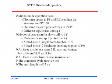
- Mixed-mode operation uses
- The same optics in P1 and P2 beamline for
- stacking and SY120
- The same major dipole settings in P1/P2
- Different dipole trim settings
- Modes of operation for slow spill to SY
- Dedicated slow spill (initial mode)
- Mixed-mode (single batch to pbar, 7/9)
- Mixed-mode (2 batch slip-stacking to pbar, 8/19)
- All three modes use same MI ramp and timing,
- but different TLG modules
- All three modes have been commissioned
- The minimum cycle time 2.8 sec
- The spill length is 655 ms
2
Optics n Such
Beams-doc-1243
400m
500m
MI
P1
P2
AP1
Stacking
Changed P1 P2 quads Q703 fixed AP1
quads fixed
F17
200m
P2
P3
SY120
Before
After
A0
Want to start with a matched solution for new SY
tune New lattice n orbit installed July 9th
3
Two flavors of Mixed-mode (1 or 2 batch to Pbar)
Pbar batches
SY120 batch
RF recapture
Beam to pbar
Qh
Beam to SY
Losses _at_F18
QXR
Simple mixed-mode
Slip-stacking mixed-mode
4
Issue losses during acceleration w/ slip stacking
3rd batch
2nd batch
1st batch
Data from Kiyomi
recapture
Need to adjust slip stacking curves to shift
recapture time to finish before SY120 batch
injected
5
Issue Orbit through F17 and losses in Tev at F18
AP1 c-magnets
F17B3
F17
F17
6-8mm oscillation in P3
-8mm
P2 line
AP1
3v
SY120
TLMF18
- Raise upstream c-magnet interface
- ( 1/3 inch) to center lower beam
- pipe on P2-P3 median plane
- Install V Trim at F18
1.75 OD
Safe level (1/4 v)
6
Issue Mixed-mode Cycle Duty Factor
TLG with 4 sec rep (with other study cycles)
Rms current H618
12 a
Trip limit
4 sec rep
5 sec rep
What to do? gtQuad moves (reduce corr.
current) gtCooling plates (as done for
NuMI)
8a
7
Issue Spill Duty Factor
QXR 20A FS
RFSPILL
MHIERR
100 ma/div
Beam
From 4/2004 RunII meeting
Recall, that the horizontal quad bus produced a
measured tune shift of0.0146 /amp gt 70 mA will
produce a 0.001 tune shift which is the
equivalent to 10 amps on QXR (2 magnets).
EE Support implemented feedback to stabilize
average level of Qh and Qv due to asymmetric TLG
- Not been focused on up to this point
- Starting point gt model system over shutdown and
- implement feedback using MHIERR as input to kHz
bandwidth - bucker system.
- Need beam studies for commission bucker system
St
Recommended
CrystalGraphics Presentations


