
Rapid Prototyping - PowerPoint PPT Presentation
Title:
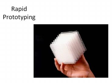
Rapid Prototyping
Description:
Rapid Prototyping powder polymers ... Platform moves up into position to ... accuracy is slightly less than that of Stereolithography and Selective laser sintering ... – PowerPoint PPT presentation
Number of Views:400
Avg rating:3.0/5.0
Title: Rapid Prototyping
1
Rapid Prototyping
2
(No Transcript)
3
(No Transcript)
4
(No Transcript)
5
(No Transcript)
6
- Rapid prototyping is the automatic construction
of physical objects using additive manufacturing
technology. - used to produce models and prototype parts.
7
Development
- Manual Prototyping by craftsman
- 1970 prototyping in CAD , virtual environment
- 1980, Rapid Prototyping (RP) by layer-by-layer
material deposition. CAD/CAM
8
(No Transcript)
9
(No Transcript)
10
(No Transcript)
11
(No Transcript)
12
(No Transcript)
13
(No Transcript)
14
- The standard data interface between CAD software
and the machines is the STL file format. - An STL file approximates the shape of a part or
assembly using triangular facets. - Smaller facets produce a higher quality surface.
- SLC Slice format, CLI Common Layer Interface
15
(No Transcript)
16
(No Transcript)
17
- Some solid freeform fabrication techniques use
two materials in the course of constructing
parts. - The first material is the part material and the
second is the support material (to support
overhanging features during construction). - The support material is later removed by heat or
dissolved away with a solvent or water.
18
(No Transcript)
19
- Advantages during development ...No tooling
costs - Short production times
- Comparatively low unit prices
- Constructional simplification e.g. instead of
housing, lid and screws, 1 complete sintered unit
can be made - Test- and functional products can be produced in
small batches - Formal- and functional variants possible
20
- ... production ...
- No tooling costs for small- and medium-sized
batches - Low tooling costs for larger batches
- Product customization possible without additional
costs - ... and the production of spare parts.
- No tooling management necessary
- Spare parts need no longer be kept but produced
as required - Unlimited subsequent delivery
21
Prototyping technologies Base materials
Selective laser sintering (SLS) Thermoplastics, metals powders
Fused deposition modeling (FDM) Thermoplastics, eutectic metals.
Stereolithography (SLA) photopolymer
Laminated object manufacturing (LOM) Paper
Electron beam melting (EBM) Titanium alloys
3D printing (3DP) Various materials
22
- Stereolithography (SL) is an additive
manufacturing technology for producing models,
prototypes, patterns, and in some cases,
production parts. - UV laser and liquid photo curable resin
- Laser cures resin
23
(No Transcript)
24
(No Transcript)
25
(No Transcript)
26
(No Transcript)
27
- can be used as master patterns for injection
molding, thermoforming, blow molding, and also in
various metal casting processes - Costly
28
- To create an SLA rapid prototype, first a
three-dimensional CAD part is "sliced"
horizontally into cross-sections between 0.002"
and 0.006" thick. - The slices are fed to 3D Systems'
Stereolithography Apparatus. Inside the
stereolithography chamber of the apparatus, an
ultraviolet laser traces the first layer of the
part on a metal platen, submerged just below the
surface of a vat of photo-sensitive polymer.
29
- Wherever the laser touches the liquid, it
solidifies. Once the layer is traced, the platen
sinks the thickness of a layer below the level of
the liquid. - A sweeper bar moves across the surface of the
last layer, making sure there is the exact amount
of resin on top. - The next layer is then built upon the previous
layer. In this manner the entire part is built
from the bottom up, with the completed sections
of the part remaining submerged.
30
(No Transcript)
31
- In the Selective Laser Sintering (SLS) process,
three-dimensional parts are created by fusing (or
sintering) powdered thermoplastic materials with
the heat from an infrared laser beam. - The objects creation is accomplished by
repeatedly fusing thin powder layers using a
laser beam. - This additive manufacturing sequence produces
parts that gradually increase in size until they
reach the prescribed dimensions. - These prototypes are created directly from 3D CAD
models.
32
(No Transcript)
33
- Selective laser sintering is an additive
manufacturing technique that uses a high
power laser (for example, a carbon dioxide laser)
to fuse small particles of plastic, metal (Direct
Metal Laser Sintering), ceramic, or glass powders
into a mass representing a desired 3-dimensional
object
34
powder
- polymers (nylon, also glass-filled or with other
fillers, and polystyrene), metals
(steel, titanium, alloy mixtures, and composites)
and green sand.
35
(No Transcript)
36
(No Transcript)
37
- A plastic filament or metal wire is unwound from
a coil and supplies material to
an extrusion nozzle which can turn on and off the
flow. - The nozzle is heated to melt the material and can
be moved in both horizontal and vertical
directions by a numerically controlled mechanism,
38
- The model or part is produced by extruding small
beads of thermoplastic material to form layers as
the material hardens immediately after extrusion
from the nozzle. - acrylonitrile butadiene styrene (ABS) polymer,
the FDM technology can also be used
withpolycarbonates, polycaprolactone, polyphenylsu
lfones and waxes.
39
(No Transcript)
40
(No Transcript)
41
- In it, layers of adhesive-coated paper, plastic,
or metal laminates are successively glued
together and cut to shape with a knife or laser
cutter.
42
- The process is performed as follows
- Sheet is adhered to a substrate with a heated
roller. - Laser traces desired dimensions of prototype.
- Laser cross hatches non-part area to facilitate
waste removal. - Platform with completed layer moves down out of
the way. - Fresh sheet of material is rolled into position.
- Platform moves up into position to receive next
layer. - The process is repeated.
43
Features
- Low cost due to readily available raw material
- Dimensional accuracy is slightly less than that
of Stereolithography and Selective laser
sintering but no milling step is necessary. - Relatively large parts may be made, because no
chemical reaction is necessary
Recommended
CrystalGraphics Presentations


