Transconductance PowerPoint PPT Presentations
All Time
Recommended
Record Extrinsic Transconductance (2.45 mS/ m at VDS = 0.5 V) InAs/In0.53Ga0.47As Channel MOSFETs Using MOCVD Source-Drain Regrowth Sanghoon Lee1*, C.-Y. Huang1, A ...
| PowerPoint PPT presentation | free to download
Adjustable Linear Range Operational Transconductance Amplifier with Noise Compensation Brian Ginsburg, Muyiwa Ogunnika Overall topology Basic WLR with bulk drive ...
| PowerPoint PPT presentation | free to download
FET BJT (Transconductance ,gm ) MOSFET (Depeletion) (Enhancement ...
| PowerPoint PPT presentation | free to view
Models of the MOSFET. Transconductance non-saturation. Transconductance saturation ... circuit modeling a MOSFET. gain. Miller capacitance. Neglect ...
| PowerPoint PPT presentation | free to download
Emitter-Follower (EF) Amplifier DC biasing Calculate IC, IB, VCE Determine related small signal equivalent circuit parameters Transconductance gm
| PowerPoint PPT presentation | free to download
Differential Amplifier with Active Load Differential-to-Single-Ended Conversion The Active-Loaded MOS Differential Pair Transconductance of the Active-Loaded MOS Pair ...
| PowerPoint PPT presentation | free to download
Good weak-strong inversion transition. Transconductance when VDS is small ... Device geometries from SPICE (table, graph); may require iteration (e.g. CGS) Sweep V1 ...
| PowerPoint PPT presentation | free to view
Bipolar Amps MOS Single Stage Amplifiers Source-Coupled Pair Fig 3.50 Assume identical devices, ... Differential Input Voltage Fig 3.51 Transconductance Gm ...
| PowerPoint PPT presentation | free to view
What is the answer to a question that Dr. Dave asks, that starts with 'Isn't'? Answer. ... d) Convert the voltage amplifier to a transconductance amplifier. ...
| PowerPoint PPT presentation | free to view
The attached narrated power point presentation examines the suitability of hybrid pi transistor model to explain transistor behaviour at high frequencies.
| PowerPoint PPT presentation | free to download
... Desensitivity. 3. Noise Reduction. 4. Reduction in Nonlinear ... Reduction in Nonlinear Distortion. amplifier transfer characteristic without feedback ...
| PowerPoint PPT presentation | free to download
... Modulate W (JFET, MESFET, HEMT) Unipolar MAJORITY Carrier device For a fixed gate voltage, we observe a NONLINEAR I-V Characteristic.
| PowerPoint PPT presentation | free to view
... small chronic impants, the power dissipation should not exceed a few hundred ... Power dissipation in the circuit is acceptable, but it is still not close to 1 ...
| PowerPoint PPT presentation | free to download
Basic MOSFET Model. Q = channel charge. L = channel length. v = carrier velocity ... Basic MOSFET Model. EE213 VLSI Design S Daniels. Threshold Voltage. VSB ...
| PowerPoint PPT presentation | free to view
Figure 7.28 (a) The active-loaded MOS differential pair. ... (c) The circuit with a differential input signal applied, neglecting the ro of all transistors. ...
| PowerPoint PPT presentation | free to download
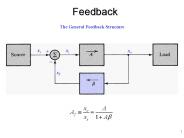
Feedback The General Feedback Structure Figure 8.1 General structure of the feedback amplifier. This is a signal-flow diagram, and the quantities x represent either ...
| PowerPoint PPT presentation | free to download
PG Embedded Systems www.pgembeddedsystems.com #197 B, Surandai Road Pavoorchatram,Tenkasi Tirunelveli Tamil Nadu India 627 808 Tel:04633-251200 Mob:+91-98658-62045 General Information and Enquiries: g12ganesh@gmail.com
| PowerPoint PPT presentation | free to download
The Nyquist Plot Effect of Feedback On The Amplifier Poles Stability Study Using Bode Plots Frequency Compensation Spice Simulation Examples * The General Feedback ...
| PowerPoint PPT presentation | free to view
Lecture 42: Review of active MOSFET circuits Prof. J. S. Smith Final Exam Covers the course from the beginning Date/Time: SATURDAY, MAY 15, 2004 8-11A Location ...
| PowerPoint PPT presentation | free to view
Lecture 20 ANNOUNCEMENTS HW#11 is due in 2 weeks, on 11/20. Review session: Fri. 11/9, 3-5PM in 306 Soda (HP Auditorium) Midterm #2 (Thursday 11/15 in Sibley Auditorium):
| PowerPoint PPT presentation | free to download
Title: Multi-functional Packaged Antennas for Next-Generation Wireless Applications Last modified by: koley Created Date: 1/18/2003 12:04:48 PM Document presentation ...
| PowerPoint PPT presentation | free to download
Effect of Feedback on the Amplifier Poles Figure 10.36: Effect of feedback on (a) ... Why and how negative-feedback amplifiers may be unstable (i.e. oscillate) ...
| PowerPoint PPT presentation | free to download
... of negative feedback to improve the signal-to-noise ratio in amplifiers. Noise Reduction ... Reduction in Nonlinear Distortion. 5. Voltage-Mixing Voltage ...
| PowerPoint PPT presentation | free to download
PS Weiss. Molecular Switches. Insert molecular switches in defects ... Is this a cooperative or single ... sec intervals (number indicated) Molecular ...
| PowerPoint PPT presentation | free to view
With a capacitive signal source induced noise voltage ... Neglecting correlation : For power optimized CMOS: Cgs(1/4)Cin , and the increase in Req is 2.5 ...
| PowerPoint PPT presentation | free to download
ECE4430 Project Presentation OPERATIONAL AMPLIFIER GROUP3 DEBASHIS BANERJEE JASON PINTO ASHITA MATHEW DESIGN SPECIFICATIONS Technology Node TSMC 0.18 m ...
| PowerPoint PPT presentation | free to view
When electron energy exceeds optical phonon frequency Eopt. electrons get effectively scattered by emitting optical phonons. Effective mass increases ...
| PowerPoint PPT presentation | free to view
Title: Lecture I: Introduction to pattern recognition Author: Fu Last modified by: oba0002 Created Date: 5/30/2002 4:00:40 AM Document presentation format
| PowerPoint PPT presentation | free to view
University of Oslo by: Hans Kristian Otnes Berge ...
| PowerPoint PPT presentation | free to download
use and develop new scanning probe microscopy techniques to address single and ... developed new means to control film and insertion points at the molecular scale ...
| PowerPoint PPT presentation | free to view
Deposit Si3N4 layer, implant Si and anneal for form n-type material Can also ... anneal 30 min at 450 C in H2/N2. Au reacts with Ga from substrate Ga vacancies ...
| PowerPoint PPT presentation | free to view
... (NML): tolerable voltage range for which we interpret the inverter output as a logic 0 NML = VIL - VOL Switch Representation Switching Dynamics Input high: ...
| PowerPoint PPT presentation | free to download
Chapter #12: Operational-Amplifier Circuits from Microelectronic Circuits Text by Sedra and Smith Oxford Publishing The College of New Jersey (TCNJ) ELC251 ...
| PowerPoint PPT presentation | free to download
Since we're introducing a new (confusing) subject, let's adopt some consistent notation. Please point ... Answer: Base width modulation (similar to CLM for MOS) ...
| PowerPoint PPT presentation | free to view
A Miller Divider Based Clock Generator for MBOA-UWB Application. Student: Yen-Chuan Huang ... The 1.7 GHz bandwidth is sufficient for three sub-bands of 500 MHz. ...
| PowerPoint PPT presentation | free to view
Lecture 17 ANNOUNCEMENTS Wed. discussion section moved (again) to 6-7PM in 293 Cory OUTLINE NMOSFET in ON state (cont d) Body effect Channel-length modulation
| PowerPoint PPT presentation | free to view
All these simplified forms are inconsistent with charge and current computed ... vendor on their own may results inconsistent results, especially for AC analysis. ...
| PowerPoint PPT presentation | free to view
Title: No Slide Title Author: U95-2 Last modified by: sfliang Created Date: 7/10/2001 10:28:53 PM Document presentation format: On-screen Show (4:3)
| PowerPoint PPT presentation | free to view
Title: Introduction to Electronics Author: Dr. Saeed Shiry Last modified by: Your User Name Created Date: 4/23/2005 6:00:39 AM Document presentation format
| PowerPoint PPT presentation | free to download
... I Aller, T Ludwig, K Kim R V Joshi, C-T Chuang, K Bernstein and R Puri, IEEE Circuits and Dev. ... Kidong Kim, et al., Japanese J of Appl. Phys., vol.43, no. ...
| PowerPoint PPT presentation | free to download
Lecture #27 OUTLINE BJT small signal model BJT cutoff frequency BJT transient (switching) response Reading: Finish Chapter 12 Small-Signal Model Small-Signal Model ...
| PowerPoint PPT presentation | free to download
Oscillators: Analysis and Designs Asst. Prof. Dr. Pipat Prommee Telecommunications Engineering Department KMITL Homepage: www.telecom.kmitl.ac.th/~pipat
| PowerPoint PPT presentation | free to view
CNT devices Since their first discovery and fabrication in 1991, CNTs have received considerable attention because of the prospect of new fundamental science
| PowerPoint PPT presentation | free to download
Lecture 13 High-Gain Differential Amplifier Design Woodward Yang School of Engineering and Applied Sciences Harvard University woody@eecs.harvard.edu
| PowerPoint PPT presentation | free to download
The control of the channel is obtained by varying the depletion layer width ... electrode reduces the effective channel depth, b(x), and therefore increases the ...
| PowerPoint PPT presentation | free to view
Chapter 2 Small-Signal Amplifiers Most amplifiers in communication circuits are small signal amplifiers. Hence, they can be described by linear equations.
| PowerPoint PPT presentation | free to view
CHC lifetime based upon 10% change in gm for NMOS devices annealed in FG and D2 for two ... Comparison of D2 and H2 annealed device characteristics. ...
| PowerPoint PPT presentation | free to view
Title: Mixed-Signal Design for Power Management and Distribution Systems for SOAC Subject: Mixed-Signal Design for PMAD for SOAC Author: blalock
| PowerPoint PPT presentation | free to download
Department of Electrical and Computer Engineering. University of ... Lift-off PMMA. CVD from methane at 1000C. 2000nm. No field. Growth in field (1V/micron) ...
| PowerPoint PPT presentation | free to download
Design of RF CMOS Low Noise Amplifiers Using a Current Based MOSFET Model Virg nia Helena Varotto Baroncini Oscar da Costa Gouveia Filho OUTLINE Introduction MOSFET ...
| PowerPoint PPT presentation | free to download
Title: Diapositive 1 Author: Giuseppe Last modified by: papadas Created Date: 2/28/2004 11:58:05 AM Document presentation format: On-screen Show Company
| PowerPoint PPT presentation | free to download
CNT devices Since their first discovery and fabrication in 1991, CNTs have received considerable attention because of the prospect of new fundamental science
| PowerPoint PPT presentation | free to download
FRIENDS and WAR Power Center for Utility Explorations The mission of the Power Center for Utility Explorations is to explore all energy issues holistically and to ...
| PowerPoint PPT presentation | free to download
Conductance in One Dimension: Nanotubes and Molecules Michael S. Fuhrer Department of Physics and Center for Superconductivity Research University of Maryland
| PowerPoint PPT presentation | free to download
N-type doping was first done using alkali metals that donate electrons to the tube. This has been used to create n-type transistors, p-n junctions, and p-n-p devices. ...
| PowerPoint PPT presentation | free to download
High-Voltage High Slew-Rate Op-Amp Design Team Tucson: Erik Mentze Jenny Phillips Project Advisors: Dave Cox Herb Hess Project Sponsor: Apex Microtechnology
| PowerPoint PPT presentation | free to view


