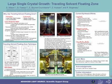
Large Single Crystal Growth: Traveling Solvent Floating Zone - PowerPoint PPT Presentation
1 / 1
Title:
Large Single Crystal Growth: Traveling Solvent Floating Zone
Description:
1 Department of Physics, University of California, Berkeley, California 94720, USA ... Holes introduced via Sr alloying or oxygen intercalation. Staged La2CuO4 y ... – PowerPoint PPT presentation
Number of Views:539
Avg rating:3.0/5.0
Title: Large Single Crystal Growth: Traveling Solvent Floating Zone
1
Large Single Crystal Growth Traveling Solvent
Floating Zone
S. Wilson1,2, B. Freelon1,2, E.
Bourret-Courchesne2,3, Z. Hussain3, and R.
Birgeneau1 1 Department of Physics, University of
California, Berkeley, California 94720, USA 2
Lawrence Berkeley National Laboratory, Advanced
Light Source, Berkeley, California 94720, USA 3
Materials Sciences Division, Lawrence Berkeley
National Laboratory, Berkeley, California 94720,
USA
Current Synthesis Efforts
Why Use Traveling Solvent Floating Zone?
Feed rod
Advantages
Experiments
- La2CuO4
- Parent compound of high temperature
superconductors - Superconductivity arises upon doping holes into
the CuO2 planes - Holes introduced via Sr alloying or oxygen
intercalation - Staged La2CuO4y
- Achieved through electrochemical doping La2CuO4
- Renders precise control of dopant disorder
- Stage-4 oxygen orders into three dimensional
crystal within the lattice - La2-xSrxCu1-yZnyO4
- Zn substitution into the CuO2 planes of
La2-xSrxCuO4 rapidly suppresses Tc - Simultaneously induces localized magnetic states
- Drastically modifies magnetism observed within
Zn-free variants
- Neutron Scattering
- ARPES (single crystal)
- Large Scale Single Crystals
- Low Contamination
Flux
Melt Zone
Canon Model SC1-MDH
- Comprised of two ellipsoidal, gold-plated
mirrors - Halogen light bulb located at either focus
generates heating zone - Temperature within the zone can reach greater
than 2100C - Extremely sharp melting zone possible
- Motorized shafts translate the raw
polycrystalline feed material through the
melting zone - Precisely controlled range of speeds (0.02 mm/hr
to 50 mm/hr) - Versatile range of stable growth rates
- Crystal growth within a sealed quartz tube
- Allows for controlled gas environment
- Capable of sustaining pressures up to 10
atmospheres - Versatile for synthesizing single crystals of a
large variety of crystalline systems
Grown Crystal
Fig. 6 Crystal Structure of La2CuO4 The atomic
unit cell for La2CuO4 is shown with the red
hatched region enclosing the lower charge
reservoir region where Sr substitutes onto the
La-site.
Growth Start
Stabilized Growth
Fig. 4 Image from stabilized growth
Fig. 3 Image from beginning of growth
This feed rod is connected to the nucleated
crystal below the heating zone via the
crystalline melt. This melt connects the two
rods by surface tension only and, in the case of
incongruent crystal growth, contains
the necessary chemical solvent. The solvent
incorporates into the feed rod, effectively
lowering its melting point and enables the growth
of a large variety of systems. The solvent
itself "travels" to remain in the crystalline
melt as the feed rod and grown crystal are
translated downward.
Traveling Solvent Floating Zone Technique
Ellipsoidal Mirrors
Fig. 7 Picture of Staged La2CuO4? Oxygen
orders in a staging pattern along the c-axis.
Stage-6 behavior is illustrated here. From B.
Wells et al., Science 277, 1067 (1997).
Learn More
M.A. Kastner and R.J. Birgeneau. Rev. of Modern
Physics, 70, 897 (1998). Chul-Ho Lee et al.,
Super. Sci. Technol. 11, 891 (1998).
Fig. 1 Mirror Image Furnace Diagram Schematic
showing the optics and positioning of furnace
components. Light from the two bulbs focused
onto junction between feed rod and nucleated
crystal
Fig. 2 Crystal Growth using TSFZ Illustration
showing the use of a solvent during the growth of
systems which melt incongruently. The grown
crystal composition results from the solvent
chosen and the systems phase diagram.
Acknowledgements
TSFZ Details
Jerry Kekos, Edith Bourret, Ipsheeta Furtado
- Compelling advantage in the absence of any
crucible contact with the crystal during growth - Eliminates crucible contamination from the
crystal's reaction with a crucible or its
environment during growth - Growth instead via a suspended polycrystalline
"feed" rod which is translated downward through
the heating zone
Further information
Sealed growth environment
Please contact SDWilson_at_lbl.gov. More
information on this and related projects can be
obtained at http//birgeneau.berkeley.edu.
Fig. 5 Photo of Canon SC1-MDH growth
assembly The two mirror enclosure seals around
the quartz growth tube.


