Entity Relationship Diagrams - PowerPoint PPT Presentation
1 / 12
Title:
Entity Relationship Diagrams
Description:
Distinction between indicative and optative models is very important: ... optative (new system) 8. York University. Department of Computer Science ... – PowerPoint PPT presentation
Number of Views:467
Avg rating:3.0/5.0
Title: Entity Relationship Diagrams
1
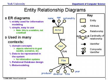
Entity Relationship Diagrams
Key
- ER diagrams
- widely used for information modeling
- simple, easy to use
- Note this is a notation, not a method!
- Used in many contexts
- domain concepts
- objects referred to in goal models, scenarios,
etc. - Data to be represented in the system
- for information systems
- Relational Database design
- Meta-modeling
age
name
nationality
Entity
Attribute
Relationship
(a,b)
(c,d)
Cardinality of relationship
(0,n)
Identifier
CompositeIdentifier
(1,n)
year
producer
director
title
2
Class Diagrams
eye
Class name
Colour Diameter Correction
aggregation
0..2
multiplicities
patient
kidney
0..1
attributes
Name Date of Birth Height Weight
Operational?
0..1
1..2
services
0..1
heart
Normal bpm Blood type
generalization
1
In-patient
Out-patient
organ
Last visit next visit physician
Room Bed Physician
Natural/artif. Orig/implant donor
3
Class associations
Multiplicity A staff member has zero or more
clients on His/her clientList
Multiplicity A client has exactly one
staffmember as a contact person
Name of the association
1
0..
liaises with
ClientList
contact person
Direction The liaises with association should
be read in this direction
Role The staffmembersrole in this
associationis as a contact person
Role The clients rolein this associationis as
a clientList
4
Association Classes
- Sometimes the association is itself a class
- because we need to retain information about the
association - and that information doesnt naturally live in
the classes at the ends of the association - E.g. a title is an object that represents
information about the relationship between an
owner and her car
0..
1
owns
owner
5
Dataflow Diagrams (DFDs)
customer query
travel request
schedule
proposed itinerary
proposed itinerary
booking request
fares
booked itinerary
tickets
booking confirmation
- Notes
- every process, flow, and datastore must be
labeled - representation is hierarchical
- each process will be represented separately as a
lower level DFD - processes are normally numbered for cross
reference - processes transform data
- cant have the same data flowing out of a process
as flows into it
6
Hierarchies of DFDs
Level 0 Context Diagram
Level 1 Whole System
customer query
customer query
travel request
tickets
Timetables
booking confirmation
schedule
booking request
proposed itinerary
proposed itinerary
Fare tables
Level 2 subprocesses
booked itinerary
fares
booking request
tickets
booking confirmation
booking request
Proposed itinerary
booking request
Req id.
Req id.
booking confirmation
seat data
booked itinerary
7
Structured Analysis
- Definition
- Structured Analysis is a data-oriented approach
to conceptual modeling - Common feature is the centrality of the dataflow
diagram - Mainly used for information systems
- variants have been adapted for real-time systems
- Modeling process
- Model of current physical system only useful as
basis for the logical model - Distinction between indicative and optative
models is very important - Must understand which requirements are needed to
continue current functionality, and which are new
with the updated system
optative (new system)
indicative (existing system)
Abstract (essential functions)
Concrete (detailed model)
8
Variants
Source Adapted from Svoboda, 1990, p264-5
- Structured Analysis and Design Technique (SADT)
- Developed by Doug Ross in the mid-70s
- Uses activity diagrams rather than dataflow
diagrams - Distinguishes control data from processing data
- Structured Analysis and System Specification
(SASS) - Developed by Yourdon and DeMarco in the mid-70s
- classic structured analysis
- Structured System Analysis (SSA)
- Developed by Gane and Sarson
- Notation similar to Yourdon DeMarco
- Adds data access diagrams to describe contents of
data stores - Structured Requirements Definition (SRD)
- Developed by Ken Orr in the mid-70s
- Introduces the idea of building separate models
for each perspective and then merging them
9
Example method SASS
Source Adapted from Davis, 1990, p83-86
- 1. Study current environment
- draw DFD to show how data flows through current
organization - label bubbles with names of organizational units
or individuals - 2. Derive logical equivalents
- replace names (of people, roles,) with action
verbs - merge bubbles that show the same logical function
- delete bubbles that dont transform data
- 3. Model new logical system
- Modify logical DFD to show how info will flow
once new system is in place - but dont distinguish (yet) which components
will be automated - 4. Define a number of automation alternatives
- document each as a physical DFD
- Analyze each with cost/benefit trade-off
- Select one for implementation
- Write the specification
10
Evaluation of SA techniques
Source Adapted from Davis, 1990, p174
- Advantages
- Facilitates communication.
- Notations are easy to learn, and dont require
software expertise - Clear definition of system boundary
- Use of abstraction and partitioning
- Automated tool support
- e.g. CASE tools provide automated consistency
checking - Disadvantages
- Little use of projection
- even SRDs perspectives are not really
projection - Confusion between modeling the problem and
modeling the solution - most of these techniques arose as design
techniques - These approaches model the system, but not its
application domain - Timing issues are completely invisible
11
UML Activity Diagrams
Receive Order
for each line item on order
failed
Check Line Item
Authorize Payment
in stock
Cancel Order
succeeded
Assign to Order
need to reorder
Reorder Item
Dispatch Order
12
Activity Diagram with Swimlanes
Order Processing
Finance
Stock Manager
Receive Order
for each line item on order
Receive Supply
Check Line Item
Choose Outstanding Order Items
Authorize Payment
failed
in stock
for each chosen order item
succeeded
Cancel Order
Assign Goods to Order
Assign to Order
stock assigned to all line items and payment
authorized
all outstanding order items filled
need to reorder
Reorder Item
Dispatch Order
Add Remainder to Stock


