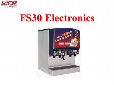
FS30 Electronics PowerPoint PPT Presentation
Title: FS30 Electronics
1
FS30 Electronics
2
POWER SUPPLY BOX
Transformer 115 to 24 VAC
115 volt input cord
Carb. Motor Relay
Transformer 115 to 16 VAC (powers
controller board and valve LED's)
Agitator Mtr. Relay
Power Switch/Circuit Breaker (7 amp)
Carbonator Motor Capacitor
28VDC and 16VDC output cable to Controller Board
(powers Control Board)
Fuse 24VAC (10 amp)
Agitator Motor Plug
Input cable from Controller Board (activates
relays)
Fuse 16VAC (10amp)
Ballast Plug
Carbonator Motor Plug
3
POWER SUPPLY BOARD
8 volts 16 volts 28 volts
Good fuse indicator light
Good fuse indicator light
Ground Test Point
Voltage Outputs
4
CARBONATOR MOTOR AND PUMP
Backflow Preventor
RELIANCE 1/4 HP Motor 115 Volt/60HZ
3.4 Amp 1675 RPM
100 GPH
Anderson Watts Brass
Clamp
Carbonator Pump
5
CUBE HEX DRIVE AGITATION ASSEMBLY
Hex Agitator Bar
Pin Ring
Hex Agitator Wheel
Hex Agitator Motor
6
CONTROLLER BOARD
Controller switches (S2 S3) must be in the RUN
position (printed on the board). If S2 is in
program position, LCD will be blank and dispenser
will not function. If S3 is in programming
position the controller will appear to work but
it can't communicate with valve boards.
LCD
Nozzle 2
Nozzle 1
Nozzle 4
Nozzle 3
Reset
X
X
X
X
X
X
X
X
X
X
X
X
X
X
X
X
X
Ice Dispense Switch
Sold-out Ports (1-8) (Not Used)
Carbonator Probe
Ice Door Solenoid
Key Switch
Keypad
Power Input (from power supply board)
Power Relay (to power supply board)
X
- Not used
7
CARBONATOR PROBE
Plugs into Main Board
White
Black
Carbonator Probe
Green
Note Probe reads between black and green wires
Carbonator Probe
8
VALVE BOARD
Receives power from controller board and sends
power to module (soda, syrup injected syrup )
coils.
Plug to Control Board
Plug to Module Coils
9
MODULE WIRING
Brands Red/Black - 1 Yellow/Black -
2 Blue/Black -3 Brown/Black -4
Injected Red/White -1 Yellow/White
-2 Blue/White -3 Soda Red/Gray
Water Yellow/Gray
W S 3 2 1 4 3 2 1
Wat Inject Brands
Module Plugs
10
MODULE COMPONENTS
24-28 VDC
11
WIRING DIAGRAM
FS 30
12
FS30 Electronics
Return to Main Menu
PowerShow.com is a leading presentation sharing website. It has millions of presentations already uploaded and available with 1,000s more being uploaded by its users every day. Whatever your area of interest, here you’ll be able to find and view presentations you’ll love and possibly download. And, best of all, it is completely free and easy to use.
You might even have a presentation you’d like to share with others. If so, just upload it to PowerShow.com. We’ll convert it to an HTML5 slideshow that includes all the media types you’ve already added: audio, video, music, pictures, animations and transition effects. Then you can share it with your target audience as well as PowerShow.com’s millions of monthly visitors. And, again, it’s all free.
About the Developers
PowerShow.com is brought to you by CrystalGraphics, the award-winning developer and market-leading publisher of rich-media enhancement products for presentations. Our product offerings include millions of PowerPoint templates, diagrams, animated 3D characters and more.

