Where Does Power Go - PowerPoint PPT Presentation
1 / 9
Title:
Where Does Power Go
Description:
Dual Vt partitioning. Effectiveness decreases at smaller L and Vt (SCE) ... Session based multiple events grouped into sessions ... – PowerPoint PPT presentation
Number of Views:36
Avg rating:3.0/5.0
Title: Where Does Power Go
1
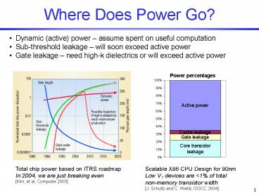
Where Does Power Go?
- Dynamic (active) power assume spent on useful
computation - Sub-threshold leakage will soon exceed active
power - Gate leakage need high-k dielectrics or will
exceed active power
Total chip power based on ITRS roadmap In 2004,
we are just breaking even Kim, et al, Computer
2003
Scalable X86 CPU Design for 90nm Low VT devices
are lt1 of total non-memory transistor width J.
Schultz and C. Webb, ISSCC 2004
2
What Are the Target Systems?
SensorInterface
I2C SPI
Sensor network node(low duty cycle, lt5)
A
D
Controller
Neighborlist
A
A
A
Cell-phone/PDAs (many inactive subsystems)
DLL
Locationing
NetworkQueues
B
A
Baseband
RF-frontend
Superscalar processors (inactive functional
units)
mP
Data flow for sensor network node
Example burst event-driven systems
- Burst data system idle times punctuated by
periods of high activity - Event-driven system functionality divided into
subsystems interacting with discrete events
3
Leakage Reduction Techniques
Vdd
sleep
HVT
pullup (Vdd)
Vdd
virtual Vdd
Wu
low Vt logic
Vnwell Vdd
Vx
Wl
virtual Gnd
Vpwell 0
sleep
HVT
dual Vt partitioning
multi-threshold (MTCMOS) Mutoh95
variable threshold (VTCMOS) Kuroda96Im03
stack effect
4
Methodology to Handle State
- Basic methodology
- Reduce state as much as possible
- Group remaining state together
- Preserve small amounts of state outside the
block - Apply to common subsystem types
Data-dominated
Control-dominated
Hybrid
Datapath
FSM
Microprocessor
Memory
EFSM
5
Types of State
- Persistent state
- State that is independent of implementation
- Must be preserved during sleep mode
- Temporary state
- State that is required for a particular
implementation (e.g. scratch registers, empty
pipeline registers, etc.) - Can be discarded during sleep mode
Illustration with multiply-accumulate circuit
Baseline version R1 contents must be kept, even
in hold mode (persistent state)
Pipelined version R2 contents can be discarded
in hold mode because known to be zero (temporary
state)
6
Power Manager Requirements
Block diagram of example power manager.
- Power manager needs to handle
- Physical composition
- Interfaces with PD power control port
- Needs to know PD signal port connections
- Temporal composition
- Must ensure PDs are active when required
- Efficiency dictates that PDs should be
powered-down when idle
7
Physical Composition (Scalability)
super PD
super PD
PD5
PD6
PD0
PD1
PD7
PD8
PD2
PD3
Local PM1
Local PM0
Global PM
Two-level hierarchical power management
architecture
- Centralized PM may cause bottleneck
- Increased latency due to simultaneous requests
- Time granularity may be different for different
subsystems - Super PDs
- Each has a local PM that controls internal
domains - Fractal nature
- Have ports just like regular PDs
- Interactions that span super PDs are sent up a
level of hierarchy - Support arbitrary depth of hierarchy and
granularity
8
Temporal Composition
- Basic schemes
- Reactive always sleep when not actively
processing - Stochastic sleep based on a probability
Simunic99 - Granularity
- Transaction based every external PD event
logged by PM - Session based multiple events grouped into
sessions - Scenario based multiple sessions grouped into
scenarios - Metrics
- Correctness PD awake when required to be active
- Efficiency minimum total energy consumption
Liao2000 - Latency time required to change modes
9
Comparing Scheduling Policies
Network
DLL
DLL
Reactive scheduling
PHY RX
PHY TX
t
Network
DLL
DLL
Scenario-based stochastic scheduling
PHY RX
PHY TX
t
PD scheduling for network packet forwarding
- Stochastic methods can give better results if
prediction is accurate - Wake-up overhead doesnt keep other PDs waiting
- PDs can spend more time sleeping
- Can prevent switching modes if would wake-up
before Min. Idle Time


