COCO Session PowerPoint PPT Presentation
1 / 14
Title: COCO Session
1
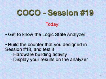
COCO - Session 19
- Today
- Get to know the Logic State Analyzer
- Build the counter that you designed in Session
18, and test it - - Hardware building activity
- - Display your results on the analyzer
2
Logic State Analyzers
- a tool for observing logic states of multiple
signals at once, in time - A logic probe can show only one bit at a time.
- Extremely useful tool for testing and debugging
sequential circuits!!
3
Summary
- Hardware version of the timing window on
LogicWorks - Capture, store, and display up to 16
time-varying signals simultaneously - Variety of ways to start/stop capture
- Make time and frequency measurements
- e.g., circuit delay measurements, setup and hold
times - Detect glitches
- More info on web
- http//www.tmo.hp.com/tmo/datasheets/English/HP54
620A.html - Manuals available in lab cabinet
4
HP54620A Specifications
- up to 500 million samples/sec
- sweep speeds of 5ns/div to 1 s/div
- about 2K bytes of data storage
- minimum detectable glitch 3.5ns
- Timebase accurate to 0.01 of reading
- can be interfaced with PCs and other instruments
- can print data
5
DISPLAY
16-BIT SIGNAL INPUT
These cables are stored behind the screens.
MICRO GRABBERS
POWER SWITCH
PROBE LEADS
6
CHANNELCONTROLS
HORIZONTAL CONTROLS
Select Channel Assign Labels Set Position
Adjust timing
7
GENERAL CONTROLS
Measuring time Saving Display and print
SOFT KEYS
Their functions change with context
8
TRIGGER KEYS
Specify kind of triggering (edge/pattern/)
TRIGGER INPUT/OUTPUT
External trigger signal Signals to trigger
external systems
9
The Screen
0
RUN
Sampling _at_ 16ns
GL
0.00s
2.00 µs/
0 Out
1 A
2 B
Activity 15 _ _ _ _ _ _ _ _ _ _ _ _ _ ???0
Ext _
Source
Edge
0 Out
E Trg In
10
Delay
Sampling Interval
Glitch Mode
0
RUN
Sampling _at_ 16ns
GL
0.00s
2.00 µs/
0 Out
1 A
2 B
Activity 15 _ _ _ _ _ _ _ _ _ _ _ _ _ ???0
Ext _
Source
Edge
0 Out
E Trg In
11
Time/div
Trigger Condition
0
RUN
Sampling _at_ 16ns
GL
0.00s
2.00 µs/
Acquisition Indicator
0 Out
1 A
One Division
2 B
Activity 15 _ _ _ _ _ _ _ _ _ _ _ _ _ ???0
Ext _
Source
Edge
0 Out
E Trg In
12
0
RUN
Sampling _at_ 16ns
GL
0.00s
2.00 µs/
0 Out
Move these using the cursor control knobs
1 A
Memory Bar
Soft Keys
Measurements
2 B
Activity 15 _ _ _ _ _ _ _ _ _ _ _ _ _ ???0
Ext _
Source
Edge
0 Out
E Trg In
13
Questions?
0
RUN
Sampling _at_ 16ns
GL
0.00s
2.00 µs/
0 Out
1 A
Manuals are in the cabinet!
2 B
Activity 15 _ _ _ _ _ _ _ _ _ _ _ _ _ ???0
Ext _
Source
Edge
0 Out
E Trg In
14
Please do the Activity Now
- Remember that the logic analyzer is a delicate
instrument. Handle it gently. Dont force
anything!! - Build and test the fancy counter that you
developed in the previous class with JK Flip
Flops (74LS109) using real TTL hardware - Display the output of your circuit on the HP
logic state analyzer

