Announcement PowerPoint PPT Presentation
1 / 24
Title: Announcement
1
Lecture 11
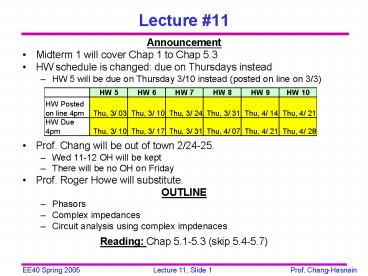
- Announcement
- Midterm 1 will cover Chap 1 to Chap 5.3
- HW schedule is changed due on Thursdays instead
- HW 5 will be due on Thursday 3/10 instead (posted
on line on 3/3) - Prof. Chang will be out of town 2/24-25.
- Wed 11-12 OH will be kept
- There will be no OH on Friday
- Prof. Roger Howe will substitute.
- OUTLINE
- Phasors
- Complex impedances
- Circuit analysis using complex impdenaces
- Reading Chap 5.1-5.3 (skip 5.4-5.7)
2
Complex Numbers (1)
- x is the real part
- y is the imaginary part
- z is the magnitude
- q is the phase
- Rectangular Coordinates
- Z x jy
- Polar Coordinates
- Z z ? q
- Exponential Form
3
Complex Numbers (2)
Eulers Identities
Exponential Form of a complex number
4
Arithmetic Operations of Complex Numbers
- Add and Subtract it is easiest to do this in
rectangular format - Add/subtract the real and imaginary parts
separately - Multiply and Divide it is easiest to do this in
exponential/polar format - Multiply (divide) the magnitudes
- Add (subtract) the phases
5
Phasors
- Assuming a source voltage is a sinusoid
time-varying function - v(t) V cos (wt q)
- We can write
- Similarly, if the function is v(t) V sin (wt
q)
6
Complex Exponentials
- We represent a real-valued sinusoid as the real
part of a complex exponential. - Complex exponentials
- provide the link between time functions and
phasors. - make solving for AC steady state an algebraic
problem. - Phasors allow us to express current-voltage
relationships for inductors and capacitors much
like we express the current-voltage relationship
for a resistor. - A complex exponential is the mathematical tool
needed to obtain this relationship.
7
Capacitor Impedance (1)
8
Capacitor Impedance (2)
Phasor definition
9
Inductor Impedance
i(t)
v(t)
L
-
- V jwL I
10
Phase
Voltage
inductor current
capacitor current
11
Phasor Diagrams
- A phasor diagram is just a graph of several
phasors on the complex plane (using real and
imaginary axes). - A phasor diagram helps to visualize the
relationships between currents and voltages. - Capacitor I leads V by 90o
- Inductor V leads I by 90o
12
Impedance
- AC steady-state analysis using phasors allows us
to express the relationship between current and
voltage using a formula that looks likes Ohms
law - V I Z
- Z is called impedance.
13
Some Thoughts on Impedance
- Impedance depends on the frequency w.
- Impedance is (often) a complex number.
- Impedance allows us to use the same solution
techniques for AC steady state as we use for DC
steady state.
14
Example Single Loop Circuit
20kW
VC
1mF
10V ? 0?
-
-
- f60 Hz, VC?
How do we find VC? First compute impedances for
resistor and capacitor ZR R 20kW 20kW ? 0?
ZC 1/j (2pf x 1mF) 2.65kW ? -90?
15
Impedance Example
20kW ? 0?
VC
2.65kW ? -90?
10V ? 0?
-
-
- Now use the voltage divider to find VC
16
What happens when w changes?
20kW
VC
1mF
10V ? 0?
-
-
- w 10
- Find VC
17
Circuit Analysis Using Complex Impedances
- Suitable for AC steady state.
- KVL
- Phasor Form KCL
- Use complex impedances for inductors and
capacitors and follow same analysis as in chap 2.
Phasor Form KVL
18
Steady-State AC Analysis
- Find v(t) for w2p 3000
19
Find the Equivalent Impedance
20
Change the Frequency
- Find v(t) for w2p 455000
21
Find an Equivalent Impedance
22
Series Impedance
- Zeq Z1 Z2 Z3
For example
Zeq jw(L1L2)
23
Parallel Impedance
- 1/Zeq 1/Z1 1/Z2 1/Z3
For example
24
Steady-State AC Node-Voltage Analysis
C
I1cos(wt)
I0sin(wt)
R
L
- Nodal analysis or mesh?
- What are the nodes (or meshes)?
- What happens if the sources are at different
frequencies?

