
Structural Analysis of PostTensioned Concrete Containment Building Repair using 3d Finite Elements PowerPoint PPT Presentation
1 / 26
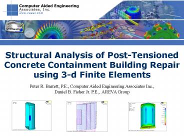
Title: Structural Analysis of PostTensioned Concrete Containment Building Repair using 3d Finite Elements
1
Structural Analysis of Post-Tensioned Concrete
Containment Building Repair using 3-d Finite
Elements
Peter R. Barrett, P.E., Computer Aided
Engineering Associates Inc., Daniel B. Fisher
Jr. P.E., AREVA Group
2
Background on Computer Aided Engineering Assoc.
- Engineering consulting firm.
- Engineering seminars including customized on-site
classes tailored to your specific needs. - WebEx interactive training available in your
office via the Web. - Custom software development.
- Provide ANSYS hotline support.
- Website www.caeai.com.
3
CAEAI Technical Staff
- Nicholas M. Veikos, Ph.D., President
- Peter R. Barrett, M.S.C.E., P.E., Vice President
- Michael Bak, Ph.D., Project Manager
- Patrick Cunningham, M.S.M.E., Project Manager
- Steven Hale, M.S.M.E., Project Manager
- James Kosloski, M.S.M.E., Project Manager
- Hsin-Hua Tsuei, Ph D. CFD Manager
- George Bauer, M.S.M.E., Project Manager
- Lawrence L. Durocher, Ph.D., Director
4
Problem
- Replacement of steam generators in nuclear power
plants may require a construction opening - A major design challenge is to develop an
efficient tendon de-tensioning and subsequent
re-tensioning plan. - Stresses and displacements must be monitored
throughout the repair sequence. - The method should simulate potential stress
mismatch between the existing wall and the patch.
5
Solution
- Nonlinear finite element analysis is simulated
using ANSYS - The sequential construction simulation includes
- Explicit modeling of the tendons and concrete
including the tendon-concrete load interaction. - Tendon tensioning, tendon loss, de-tensioning and
subsequent re-tensioning - Direct modeling of the construction opening and
repair - Modeling method captures local bending response
in the patch that can be neglected in simplified
models
6
Procedure
- Scripted Input Files are used to
- Model a symmetric portion of the building
(typically 180 degrees or less) - Model the hoop and vertical tendons explicitly
with truss elements. - Model the equipment hatch area and evaluate its
contribution to the buildings overall state of
stress. - Model the removal of individual tendons (hoop or
vertical). - Vary an individual tendons force (hoop or
vertical) - Include the effects of tendon loss for both
vertical and horizontal tendons - Scripted input allows for
- Quick What-if design changes
- Optimization of tendon tensioning and
de-tensioning
7
Finite Element Modeling
- 3-d brick elements model the concrete building
- Capture nonlinear through-thickness stresses
- 1-d truss elements model the tendons
- Explicit modeling of hoop and vertical tendons
- Stiff Spring elements connect the
prepatch-building Interface - Used in the pre-patch analysis to simulate a
continuous building - Contact elements simulate the patched-building
repair - Use to simulate the reduced patch-wall bond
strength
8
Example Simulation
- The remaining presentation represents the
trypical response that one may see in evaluating
a post-tensioned nuclear containment building. - The geometry and loading do not represent any
real building. - The purpose of the example is to demonstrate the
response that may be seen in actual containment
buildings
9
Sample Parametric Input
- ! Loads to be solved 1 solved 0 skipped
- !
- LS_11 ! 1.0 Building Dead Load 1.0
Tendons 1.0 Crane - !
- LS_21 ! 1.0 Dead 1.0 Tendons 1.0
Crane 1.5 pressure - LS_61 ! Hole in Wall
- ..
- LS_140 ! 1.0 DL 1.09v1.24H
1.5pressure - !
- D_scal1.01 ! global scaling dome loads
- H_scal1.01 ! global scaling hoop tendons
- V_scal1.01 ! global scaling vert tendons
- !
- !!!!!!!!!!!!!!!!!!!!!!!!!!!!!!!!!!!!!!!!!!!!!!!!!!
!!!!!!!!!!!!!!!
- !!!!!!!!!!!!!!!!!!!!!!!!!!!!!!!!!!!!!!!!!!!!!!!!!!
!!!!!!!!!!!!!!!!!!! - ! Pressure Loading - By Load Step
- !
- P_sc_ls288.51.4 ! Press Loading (psi) for
load step 2 - P_sc_ls31e-9 ! Press Loading (psi) for
load step 3 - P_sc_ls1488.51.4 ! Internal Pressure
Loading (psi) for load step 14 - !
- ! Define Bottom Elevation for Hole
- !
- !bot_hole-1 ! use -1 for no hole
- bot_hole859.75
- !
- ! Define Top Elevation of for Hole
- !
- !top_hole-1 ! use -1 for no hole
- top_hole859.7523.41667
- ..
10
Brick elements - building, abutments, patch
11
1-d truss elements to model the tendons
This is modeled explicitly for each tendon using
an initial strain approach that produces the
corresponding tendon force.
12
1-d truss elements to model the tendons
Solid and Truss Nodes line-up for coupling in
non-axial directions
Axial Tendon Displacements are fixed
13
1-d truss elements to model the tendons
Max. Tendon Load at Abutment
14
Example Solution Sequence
- LS 1 Dead Load Tendon Loads Equipment
Loading - LS 2 Dead Tendons Equipment Accident
- LS 3 Dead Tendons Equipment
- LS 4 Tendons de-tensioned in hole only -
vertical and horizontal - LS 5 Tendons de-tensioned locally away from
the hole - LS 6 Create the hole in the wall
- LS 7 Remaining vertical tendons detensioned as
necessary - LS 8 Patch installed stress free
- LS 9 Patch installed and contact elements
activated - LS 10 Springs removed
- LS 11 Partially re-tension verticals tendons
- LS 12 Partially re-tension hoop tendons
- LS 13 Fully re-tension hoop and vertical tendons
- LS 14 Fully re-tensioned hoop and vertical
tendons Accident
15
Vertical Stress - Gravity Tendon Loads LS1
16
Hoop Stress Gravity Tendon Loads LS1
17
Vertical Stress Hole Reduced Tendons LS7
18
Hoop Stress Hole Reduced Tendons LS7
19
Hoop Stress Repair Re-Tension LS13
20
Vertical Stress Repair Re-Tension LS13
21
Non-linear Contact Response
22
Time History Solution
23
Comparison to Path Independent Loading
Path Dependent Step-by-Step
Path Independent All loads applied at once
24
Summary of Path Dependent Loading
- Time History Simulation illustrates loading
sequence - Comparison between path dependent solution and
path independent solution show - Reduction in compressive hoop stress in the patch
region caused by the repair sequence - Potential vertical tensile stresses in the patch
region that are predicted only by including the
sequential loading - Higher tendon re-tensioning is often required in
the patch to design for this effect.
25
Sequential Illustration Simple Wall Model
- Load the wall under uniform axial displacement
(The axial compression replicates the effect of
the tendon loads) - Measure the stress state in
the pre- repaired wall. - Reduce the displacement and create a hole in the
wall simulating the creation of the construction
opening. - Patch the hole under the same reduced
displacement (Use element birth) - Increase the loads (uniform axial displacement)
back to its original values (This replicates the
re-tensioning of the tendons) and compare with
original wall
26
Illustration Load, Hole, Patch Re-load
27
Sequential Illustration Simple Wall Model
28
Conclusions
- A nonlinear incremental finite element based
stress analysis predicts stresses that would not
be captured using a non-path dependent simulation - Explicit modeling of the tendons and abutments
accurately capture force, displacement and stress
results. - Step-by-step loading provide the ability to
extract intermediate results - Using element Birth and Death captures the true
response of creating and repairing construction
openings. - An automated analysis file with user-friendly
input parameters allow the designer to perform
design iterations without becoming an analysis
expert
Recommended
