Program of Ship Salvage Engineering POSSE Introduction PowerPoint PPT Presentation
1 / 14
Title: Program of Ship Salvage Engineering POSSE Introduction
1
EN358Ship Structures
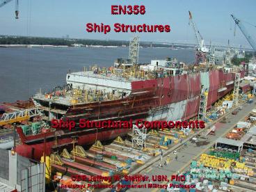
Ship Structural Components
CDR Jeffrey W. Stettler, USN, PhD Assistant
Professor, Permanent Military Professor
2
- Ships Structures are unique for a variety of
reasons. For example - Ships are very BIG structures!
- The shape of a ship is optimized for reasons
other than just structural strength. What else
is it optimized for? - Navy ships operate in a wide variety of
environments and see a variety of static as well
as dynamic/random loads. What kinds of loads?
3
- A ship structure consists of a network of welded
together cross-stiffened plates (sometimes
referred to as a grillage). - Plates are stiffened by welded girders (I-beams,
T-beams, etc.).
4
- Keel - Longitudinal center plane girder along
bottom of the ship - The ships backbone
- Plating Thin pieces closing in the top, bottom,
and sides of structure. - Outer plating (side shell and bottom plating)
- Strakes longitudinal rows of outer plating
(e.g. garboard, sheer, deck strakes) - Deck plating, inner bottom plating
- Bulkheads (longitudinal transverse)
5
- Longitudinals Stiffeners which run
longitudinally (parallel to the keel) along the
bottom of the ship. Used to longitudinally
stiffen the outer bottom plating. - Stringers Stiffeners which run longitudinally
along the sides of the ship. Used to stiffen and
strengthen the outer side shell plating. - Deck Girders Stiffeners which run
longitudinally under decks. Used to stiffen and
strengthen deck plating.
6
- Frames Stiffeners which run transversely from
keel to main deck. Used to transversely stiffen
and strengthen the outer plating. - Floors Larger portion of the frames which run
from the keel to the turn of the bilge. Used
also as foundations for inner bottom plating. - Deck beams Stiffeners which run transversely
under decks. Used to stiffen and strengthen deck
plating.
7
- Types of framing systems
- Transverse Framing
- For combating primarily hydrostatic and side
impact loads - Closely spaced continuous frames with widely
spaced longitudinals - Used primarily for
- Short ships (lengths less than typical ocean
waves 300ft) - Submarines
- Thick side plating is required
- Longitudinal strength is relatively low
8
- Types of framing systems
- Longitudinal Framing
- For combating primarily longitudinal bending
(flexure) loads - Closely spaced longitudinals and more widely
spaced (deep web) frames - Side plating is comparably thin primarily
designed to keep the water out
9
- Types of framing systems
- Combination Framing
- For combating combined loads
- More longitudinal members near top and bottom
structure - Side structure is primarily transverse WHY?
- Most Navy surface ships are of this type
10
- Single Bottom Construction
- Usually found on tankers small ships
- Bottom transverse frames are known as floors
- Floors are vertical structural members!
- Floors support bottom plating - transfer the load
to keel ( keelsons) and side frames - Can be used with any framing system
11
- Double Bottom Construction
- Advantages over Single Bottom Construction
- Stronger - provides more longitudinal material
- Provides volume in which to store liquids without
taking up cargo space - Provides damage resistance in the bottom
- Disadvantages
- More expensive to construct, higher maintenance
costs - Moves neutral axis of the ship down - causing
higher stresses in the deck
12
- Structural Drawings
- Midships Section
- Deep Frame, Scantlings
175,000 DWT TankerLWL 1027 ftB 158 ftD
83.75 ftT 54.25 ft
13
- Structural Drawings
- Midships Section
- Deep Frame, Scantlings
105,000 DWT BulkerLWL 818.3 ftB 124.7 ftD
69 ftT 50.75 ft
14
- Structural Drawings
- Midships Section
- Scantlings
20.4 plate 1/2 inch thick
Deck Stringer
Sheer Strake
Weld Seam Symbol
DD-963Simplified midship section showing shell
plate straking plan
Bilge Strake
Garboard Strake

