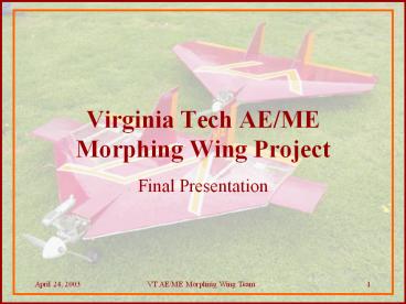
Virginia Tech AE/ME Morphing Wing Project PowerPoint PPT Presentation
1 / 27
Title: Virginia Tech AE/ME Morphing Wing Project
1
Virginia Tech AE/ME Morphing Wing Project
- Final Presentation
April 24, 2003 VT AE/ME Morphing
Wing Team 1
2
Morphing is defined as a change in the aircrafts
physical characteristics
- Smooth shape change of wing surfaces
- More efficient flight
- Reduced radar cross-section
Soar, observe
Maneuverability
3
There are two main types of morphing
Mission Morphing
Control Morphing
- Aspect ratio change
- Area change
- Dihedral change
- Camber change
- Twist change
- Continuous control surface change
4
Our first control morphing idea was to use
linkages off the servo to provide deflection
- Pros
- Simple to actuate
- 180O deflection
- Good Mechanical Advantage
- Cons
- Weak
- Not enough room to fasten links
5
Further analysis showed that an interlocking and
jointed rib provided more reliable actuation
- Pros
- Increased Stability
- Easy to assemble
- Cons
- Reduced deflection (30O)
- Requires more actuator force
6
Time constraints and technical difficulties
forced a decision to only go with mission
morphing design
- The laser cam broke
- Time restraints
- Decided to buy same kit and alter as
needed
7
BetaMax construction was modeled after the Delta
Vortex design
- Removed last rib
- Added telescoping wing
- No CG change mechanism
8
A comparison of the structural differences
between the Delta Vortex and the BetaMax
9
Static stability provides clues to flight
characteristics
Neutral point and center of gravity are measured
from the trailing edge
10
The telescoping wing was a preliminary design
concept last semester
- Increased wingspan benefits landing and
low-speed cruise - Retract for increased maneuverability
11
The telescoping wings were developed in several
stages
- Wings were hot-wire cut from R7 insulation foam
- The foam was coated in fiberglass to make a rigid
structure - Finally, plastic guide tubes were inserted by
drilling out the foam - The guide tubes ride on twin aluminum rails that
are anchored within the plane
12
A bi-lateral rack and pinion coupled to a slider
crank mechanism was used to move the wings
- Custom acrylic housing for the dual rack and
pinion system - Servo with the stops removed is used to run the
wings in and out - Kill switches maintain a maximum distance of
travel
13
Balance calculations were performed prior to
first flight
- Delta Vortex I
- Center of Gravity is 22 inches from trailing edge
- Neutral Point is 19 inches from the trailing edge
- 8 Stability
- Beta Max II
- Center of Gravity is 20.5 inches from trailing
edge - Neutral Point is 19 inches from the trailing edge
- 4.7 and 7.4 Stability in/out
- Surface Area Wings 15
14
We will collect data to compare all of our designs
Physical Data
Performance Data
- Accelerations
- Body rates
- Airspeed
- Control surface deflections/forces
15
We needed a variety of instruments to find flight
characterization data
- Pitot tube/Pressure Transducer dynamic pressure
- Accelerometers accelerations, forces
- Gyros body angular rates
- Potentiometers - to measure control surface
position
16
We found off-the-shelf items that will provide us
with the necessary data
Crossbow CXL-10LP3 Triple Axis Accelerometer
Crossbow AD2000 Data Logger
17
We found off-the-shelf items that will provide us
with the necessary data
Dwyer Standard Model 1/8 pitot tube along with
Dwyer Differential Pressure Transducer
Analog Devices Piezo-Electric Gyroscope
18
We found off-the-shelf items that will provide us
with the necessary data
Signal Conditioning Circuitry on a breadboard
Radio Shack 5K-ohm potentiometer
19
We instrumented each aircraft to record data
Delta Vortex
20
We instrumented each aircraft to record data
Beta Max
21
Signal conditioning was necessary for several of
the instruments
22
During the flights, we successfully collected
data from each of the instruments
Delta Vortex loop and roll
23
During the flights, we successfully collected
data from each of the instruments
BetaMax Roll
24
Two flight attempts were performed with the
BetaMax
- Improper balancing resulted in a failed first
flight
- BetaMax (version 1.0) vs. Delta Vortex
- 50 heavier
- 30 less elevon area
- 5 more statically stable (harder to rotate)
25
The balance and weight problems were easily fixed
by removing the added weight
- Reduced weight by 2 lbs
- Moved CG further back, lessening static margin
- Constructed new elevons with 11 more area than
those of the Delta Vortex
Unfortunately, other problems arose
26
We have accomplished most of our goals for this
year
- Build and fly a conventional delta wing
- Gather performance data from conventional delta
wing - Build and fly morphing delta wing
- Gather performance data from morphing delta wing
- Compare data
27
We plan to fly the Delta Vortex and the BetaMax
one more time
- Will fly specific flight paths with both aircraft
- Fuel consumption will be measured and compared
- Data will be analyzed
- by future teams
Questions?

