
Design of a Simulink 2DOF Robot Arm Control Workstation PowerPoint PPT Presentation
1 / 43
Title: Design of a Simulink 2DOF Robot Arm Control Workstation
1
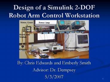
Design of a Simulink 2-DOF Robot Arm Control
Workstation
- By Chris Edwards and Emberly Smith
- Advisor Dr. Dempsey
- 5/3/2007
2
Presentation Outline
- Project Summary
- Quansar System
- SimMechanics Modeling
- System Identification (ID)
- Controller Design Results
- Load Testing
- Overall Block Diagram
- Graphical User Interface (GUI)
- Virtual Reality (VR) Workstation
- Demonstrations
- Comparison of Results
- Questions and Discussion
3
Project Summary
- Actual Robot Arm
Virtual Robot Arm
4
Equipment and Parts List
- Quansar Workstation
- Software
- MATLAB
- Simulink
- SimMechanics
- Guide
- Virtual Reality Toolbox
- Real-Time Workshop
5
Previous Work
- Vaccari and Osterholts Project Achievements
- Modeling the robot arm in SimMechanics Toolbox
- Designing closed-loop controllers
- Real time visualization using the Virtual Reality
__Toolbox - Implementing force feedback joystick control
- Note Non-inverting configuration was used with
no load.
6
Project Goals
- Add rotary flexible joint to the existing system
model - Validate new model through experimental results
- System identification
- Design closed-loop controllers for software model
- Basic proportional controller
- Lag/lead controller using optimum phase margin
design - Advanced multi-loop feed forward controller
- Implement controllers into experimental
workstation - Test and compare controller results
- Create a graphical user interface to simplify
user interaction - Make additions to previous virtual reality
workstation
7
Progress Report
8
Quansar System
2-DOF
Arm
Base
1-DOF
Gears
Motor
Stand
9
Functional Description
- Mass-Damper-Spring System
- Mass
- Arm
- Gripper
- Load
- Damper
- Friction will act as the damper
- Spring
- Springs attach the robot arm to the base
10
VR Robot Arm Model
11
VR Gear Train Model
12
SimMechanics Model
13
Rotary Joint with Springs
Body Anchor Points Both A r 3.18 cm d
3.18 cm Arm Anchor Point 3 R 7.60 cm Spring
Type 1 Length 2.54 cm Spring Constant
220 N/m
14
2-DOF Robot Arm
15
2-DOF Robot Arm Model
16
System Identification
ke-sTd__ s(s/p 1)
- Plant Type
- Second Order
- Time Delay
- Find Gain (k)
- Find Time Delay (Td)
- Find Pole Location (p)
Gp
17
System ID Results
SimMechanics Model
System ID Model
18
Proportional Controller
Lag/Lead Controller
19
Feed Forward Controller
20
Open Loop Step Response
21
Closed Loop Step Response
22
Final Controller Results
23
Progress Report
24
Load Testing
25
Workstation Design
26
Overall Block Diagram
27
Matlabs Guide
28
Controller Switch Structure
29
GUI Layout
30
V-Realm Builder
31
Virtual Reality Workstation
32
Virtual Reality Springs
33
Open-Loop Workstation
34
Advanced Controller
35
OPM Controller Results
36
Advanced Controller Results
37
Questions?
2-DOF
Arm
Base
1-DOF
Gears
Motor
Stand
38
Appendix AMechanical Specifications
39
Appendix BModeling Linear Friction
40
Appendix COptimum Phase Margin Design
- -utilizes the derivative of the phase angle
equation in order to place ?c at the peak of the
phase curve insuring optimal stability over a
maximum range - ßc -p (p/2 - ?c/?1) - (?c/?1) ?cTd - ?cT/2
- dßc/d?c ?1/?c2 - 1/?c - Td p/?s
41
Appendix COptimum Phase Margin Design
42
Appendix D Signal Conditioning
43
Appendix E Controller Results
Recommended
