
Pad Response Function PowerPoint PPT Presentation
1 / 7
Title: Pad Response Function
1
Pad Response Function
- Motivation There was a disagreement between
calculated (Mathieson Formula) and measured pad
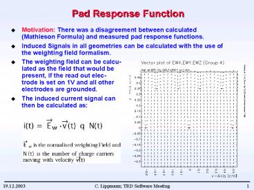
response functions. - Induced Signals in all geometries can be
calculated with the use of the weighting field
formalism. - The weighting field can be calcu-lated as the
field that would bepresent, if the read out
elec-trode is set on 1V and all otherelectrodes
are grounded. - The induced current signal canthen be calculated
as
2
Pad Response Function
- Simulation is done with GARFIELD
- Mathieson Formula gives smaller value of sigma
- The difference is explained by the fact that one
cathode plane is made of wires.
3
Drift Time Map for AliRoot
- GARFIELD, Va 1.55kV, Vd-2.1kV, Xe-CO2 85-15.
4
Average Drift Velocity
- Average drift velocity is not homegeneous
5
Average Drift Velocity
- Try to implement this for a correction of the
beam data
6
Residuals on the Track
- There is definitely some distortion through the
non-constant average drift velocity
7
Extend Time Bins in Amplification Region
15deg 0.8deg ? 0.66deg 10deg 0.68deg ?
0.6deg 5deg 0.54deg ? 0.54deg 0deg 0.49deg
? 0.36deg
Recommended
