Autonomous Helicopter PowerPoint PPT Presentation
1 / 13
Title: Autonomous Helicopter
1
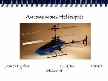
Autonomous Helicopter
James Lyden EE 496 Harris Okazaki
2
Project Overview
- The goal of this project is to create a
helicopter capable of flying itself. The
helicopter should be able to take off, fly to a
predetermined location, and land without user
input (during flight). The target will be
specified pre-flight by a user, through a
computer interface.
3
Hardware Modules
- Onboard Controls
- Master Microcontroller
- Slave Microcontroller
- Sensors
- Accelerometer
- Gyroscope
- Communications
- Bluetooth Transceivers onboard and on PC
- PID Correction System
- PC
4
Block Diagram
OFFBOARD
ONBOARD
5
Software Flow
PC Software Flow
6
Software Flow
Master µC Software Flow
7
Software Flow
Slave µC Software Flow
8
Focus Accelerometer Interface (components)?
- Digital Interface
- Microcontroller I²C Master
- Accelerometer I²C Slave
- ADC performed by accelerometer
- All data transfer performed via register
read/write - Wiring
- SCL clock, synchronizes data rate
- SDA Bidirectional data line only one device can
transmit at a time, negotiated by I²C protocol
9
Focus Accelerometer Interface (tests)?
- Communications test
- Read the WHO_AM_I register, verify it reports
known value - Write config data to CTRL_REG1, read to verify it
worked - Scale test (once per axis)
- Tilt sensor so target axis is subject to gravity,
read the value of each axis, verify target axis
is roughly 1g while other axes are roughly zero. - Speed test
- Read values from all 3 axes at a rate of 2.56KHz
(delay 390 µs between reads), ensure data changes
as we tilt sensor
10
Focus Accelerometer Interface
11
Focus Accelerometer Interface (design decisions)?
- Using digital vs. analog interface
- Analog interface would have required using
microcontroller's ADC, which would also be
occupied by gyroscope - Analog interface used 3.3V logic, limiting the
full range when coupled to the 5V microcontroller
ADC - Less ADC code interspersed through the
microcontroller code - Using I²C vs. SPI
- SPI uses 4 wires, where I²C only requires 2
- Using one 3-axis device vs. multiple single-axis
devices - Size and weight constraints, as well as wiring
complexity
12
Remaining Work
- Testing
- Gyroscope digital interface
- Master microcontroller loop speed
- We need to know if the loop runs faster than ADC
- Refinement
- PID scale tuning
- Optimize code in master microcontroller main loop
- If we have time, increase baud rate for serial
communications - Implementation
- Accelerometer interface (partially done)?
- User interface
13
Gantt Chart

