
Ground Based 2DoF Test for LISA and LISA PF PowerPoint PPT Presentation
1 / 1
Title: Ground Based 2DoF Test for LISA and LISA PF
1
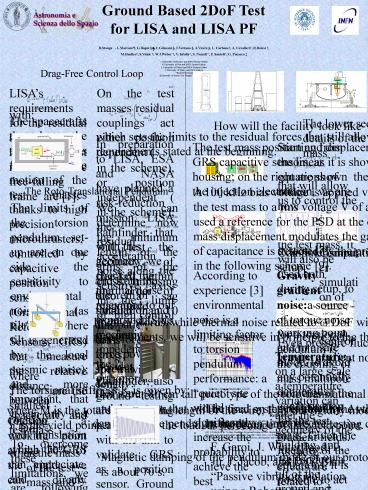
Ground Based 2DoF Test for LISA and LISA PF
R.Stanga , L.Marconi , G.Bagni , C.Grimani ,
F.Vetrano , A.Viceré , L. Carbone, A.
Cavalleri, R.Dolesi , M.Hueller, S.Vitale ,
W.J.Weber , V. Iafolla, S. Nozzoli, F.
Santoli, G. Pucacco University of Florence
and INFN Firenze-Urbino University of Pisa and
INFN Firenze-Urbino University of Urbino and
INFN Firenze-Urbino University of Trento and
INFN Padova INAF-IFSI Roma University of Roma
Tor Vergata and INFN Roma
Drag-Free Control Loop
LISAs requirements for the residual acceleration
noise of the test masses in the free-falling
frame are 1
On the test masses residual couplings act either
position dependent ( in the scheme), or
position independent ( in the scheme) the
residual acceleration
noise along the sensitive axis, in the limit
of high control loop gain,
, is given by
with
The spacecrafts that host the test masses follow
the motion of the test masses thanks to high
precision microthrusters, controlled by
capacitive position sensors (Gravitational
Reference Sensors, GRS) that measure the relative
distance between spacecraft and test mass.
The lower section of the vacuum vessel,
with details of the holder of the sensor of the
test mass
How will the facility look like
which sets the limits to the residual forces that
still allow to mantain the requirements stated
at the beginning.
In preparation to LISA, ESA and NASA have planned
a risk-reduction mission, LISA Pathfinder, that
will test the accuracy of free-fall, within one
order of magnitude from LISAs requirements.
Besides LISA Pathfinder, also ground testing
are being performed, with the aim to validate GRS
as a position sensor. Ground tests make use of a
torsion pendulum bench 3, where a lightweight
LISA test-mass is suspended by a thin wire. The
displacement of the test mass is monitored both
by capacitive sensor and by optical methods, and
is controlled with capacitive actuation. This
test bench simulates the free-fall condition for
1 DoF within two orders of magnitude from LISA
2,3.
Starting from the linear equations of motion, we
are now implementing a linear control system 7
The test mass position and displacement are
monitored and controlled by GRS capacitive
sensors, as it is shown in the figure on the
left, the sensor housing on the right are shown
the electrodes that act on each axis in red
are the injection electrodes.
that will allow us to control the rotation and
the displacement of the test mass. It will also
be used both during setup, to position the test
mass on the working point, and in a safe mode, to
avoid any potentially dangerous configuration for
the test mass. Given the linearity of the
equations, it is possible to act directly on q
and ? .
The Roto-Translational Pendulum
A 100 kHz bias voltage is applied via the
injection electrodes, that keep the test mass to
a rms voltage V of about 0.6 V. The same signal
is also used a reference for the PSD at the
output of the pre-amplifier. The test mass
displacement modulates the gap of the capacitors,
and the variation of capacitance is detected by
the pre-amp, with a bridge circuit as shown in
the following scheme 9.
- The limits of the torsion pendulum set-up are on
one side the sensitivity to environmental noise
(as tilt/twist, where tilt is generated by the
local seismic noise) and, more important, that
it can only test 1 DoF. - To overcome these limitations, we are following
two strategies. First, we have found a quiet
site at a location in Laboratorio Nazionale del
Gran Sasso (LNGS), where we will locate the new
test bench. - Second, we are developing a 2 DoFs system, which,
after considering a number of many DoFs
geometries (Scott linkage, Roberts
linkage7,8), will be a roto-translational
pendulum. The 2 DoFs (see the sketch below) are
the rotation ? around the central suspension
wire, and q- ?, where q is the rotation around
the lateral suspension wire. The angle ? at the
test mass level translates to a linear
displacement y, in the limit of small angles. - With the 2 DoFs roto-translational pendulum we
will be able to - Close feedback loops simultaneously on more than
one DoF. - Close feedback loop on one DoF and measure the
effects along the other DoF. - Measure the stiffness and cross-stiffness with
closed feedback loops. - Test actuation cross talk with closed feedback
loops in particular, to measure the residual
disturbance along the sensitive translational
axis when we close the control loop along the ?
rotation . - Verify the dc stray voltage compensation
technique simultaneously in different DoFs 6,
10. - Verify the compatibility of the charge
measurement by means of a dithering voltage
applied in terms of noise induced in y 6,
10. - In the design, we first determined the torsional
stiffnes needed to meet our requirements (that we
optimistically take to be LISA PF requirements)
We can determine now the minimum length of the
arms of the cross. Imposing also a sag smaller
than 10 mm for the arms of the cross, we get,
for W wires 1 m long
With this geometry, we checked the thermal noise
relevance to our experiment the mechanical
impedences for the 2 orthonormal DoFs are
Computer simulation of controlled setup
Computer simulation of safe mode control
According to experience 3 environmental noise
is a limiting factor to torsion pendulum
performance a quiet site would significantly
increase the probability to achieve the best
performances and would simplify the efforts
needed to reduce the environmental disturbances
in term of shielding (temperature, magnetic
field) and in terms of active control
(temperature, floor tilt), and could result in a
better design with a high degree of immunity to
Newtonian noise. The most relevant environmental
noise sources are Seismic noise microseism of
laboratory floor can induce a stray torque on the
pendulum through several mechanisms 3. Any
tilt motion of laboratory floor can induce a
torque on the pendulum through any position
dependent torque induced by the GRS itself, or
the effect of linear cross-coupling of suspension
point tilt into pendulum twist. Linear microseism
of the suspension point of a torsion pendulum may
couple swinging modes into torsional modes. Also
vertical microseismic noise can couple into
pendulum twist via nonlinearities in the wire
response to vertical spring-type modes of the
pendulum3,4,6.
Gravity gradient noisea source of torque noise
for a torsional pendulum is the coupling of mass
multipole moments of the pendulum to gravity
gradient fields. As these effects are related to
changing ambient mass distribution, one expects
that lower seismic noise, better environmental
temperature stability and better isolation from
weather condition will produce a more benign
gravitational ambient 11,12,14. Operating
the roto-translational pendulum at LNGS will give
us the opportunity to measure the relevance of
this source of noise.
and from the theorem of fluctuation and
dissipation we have for the force power spectral
density
In other words, while thermal noise related to ?
DoF will not be a limit to our measurements, we
will be sensitive in principle to the thermal
noise of (q ? ) DoF.
Even pressure fluctuations due to weather are a
relevant source of gravity gradient noise 11.
Temperature on a large scale a temperature
variation can alter the geometry of the building,
and itself induce a tilt of the ground and
Newtonian noise. Since the best approach to
eliminate environmental disturbances in a
measurement requires reducing the effect where it
originates, the choice of the experimental site
is important and must be made with care. Low
microseism, stability in temperature and air
pressure on time scales exceeding a day qualify
the site for the experiment. The environmental
stability of an underground site has been already
identified as a promising option for
gravitational wave detectors and torsion pendulum
for experimental gravity. Laboratori Nazionali
del Gran Sasso is a good candidate, if adequate
attention is paid to isolation from human
activity. Temperature and pressure are stable on
long timescales, and measurements over many years
show that, at low frequencies, tilt microseismic
noise is at least 5 times lower than in ground
floor laboratory 13.
where , are the smallest
rotation and translation
which the GRS can appreciate, and
are, respectively, the stiffnesses of the
lateral and central wire
The torsional stiffness K is given by
This is our 80 cm tall prototype of the
roto-translational pendulum, with the test mass
and the sensor that will be used on the real
facility. At the top there is a magnetic damper
for the pendulum mode.
Seismic measurements at LNGS
The final system is now in the workshop it will
be ready by autumn, in time with the setting up
of the site at the Laboratori del Gran Sasso. In
the mean time, we are testing components and
control algorithms on our prototype in Firenze.
where M is the total load, L is the length of the
wire, F is the rigidity modulus, Y is the yield
point, and C Y is the load, as percentage of the
yield point.
References
Chosing a working point at the 70 of the yield,
we can direcly calculate the parameters of the
wires
1 S.Vitale et al, LISA and its in flight
test precursor SMART-2, Nuclear Physics B, vol.
120, pp. 210, 2002 and references therin 2
R.Dolesi et al, Gravitational sensor for LISA
and its technology demonstration mission, Class.
And Quant. Grav., vol. 20, pp. S99, 2003 3
M.Hueller, A.Cavalleri, R.Dolesi, S.Vitale and
W.J.Weber, Torsion Pendulum Facility for ground
testing of gravitational sensors for
LISA, Class. And Quant. Grav., vol. 19, pp.
1757, 2002 4 C.D.Hoyle et al, 4-Mass
Pendulum for ground testing of LISA
displacement, in Proc. Marcel Grossman Meeting,
2003 5 Y.Su et al, New test of the
universality free fall, Phys. Rev., vol. D50,
pp. 3614, 1994 6 M.Hueller, Geodesic motion
of LISA test masses development and testing of
drag-free position sensor, PhD degree thesis,
Trento 2003 7 F. Garoi, J. Winterflood, L.
Ju, J. Jacob, and D.G. Blair, Passive vibration
isolation using a Roberts linkage 2003 Rew. Sci.
Instr. Vol 74, 3487. 8 F. Biral, D.
Bortoluzzi, M. Da Lio, Dynamical optimization of
a Roberts Linkage-based inertial isolation for
gorund testing of a scientific space mission
critical phase, in ECCOMAS thematic Conference
Multibody Dynamics, 2005 9 W.J. Weber et al,
Class. Quantum Gravity, 2002, Vol 19, 1751 10
L. Carbone, Ground based investigation of force
noise sources for LISA, PhD degree thesis,
Trento 2005 11 V. N. Rudenko, A. V.
Serdobolski, K. Tsubono, Atmospheric gravity
perturbations measured by a ground-based
interferometer with suspended mirrors, Class.
And Quant. Grav., vol. 20, pp. 317-329. 12
Shuichi Sato et al. Ultra-stable performance of
an underground-based laser interferometer
observatory for gravitational waves 13 V.
Iafolla, V. Milyukov, S. Nozzoli,Tidal tilts
observations in the Gran Sasso undeground
laboratory 2001, Il Nuovo Cimento, vol 24C,
263 14 R. DeSalvo,.Mining for gravitational
waves, 2004 Aspen Winter Conference on
Gravitational Waves
where
is the mass of the test mass, and
is the total mass.
Magnetic damping of the pendulum mode of our
prototype the decay time is about 70 s.
Recommended
