
Structural Modeling of Flames for a Production Environment PowerPoint PPT Presentation
1 / 36
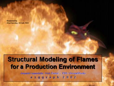
Title: Structural Modeling of Flames for a Production Environment
1
Presented by
Ohad Barzilay, CG Lab, HUJI
Structural Modeling of Flames for a Production
Environment
Arnauld Lamorlette, Nick Foster - PDI /
DreamWorks
s i g g r a p h 2 0 0 2
2
Motivation
- Realistic Flame Simulation
- Controllable Look and Behavior
3
Previous Work
- Direct numerical
- simulation
Visual Modeling
Realistic results
Very controllable
- Flames Shape Motion control
- Realism depends on Animator
4
New Model
- A general fire animation tool with 8
- components each can be either
- directly controlled by animator, or
- driven by a physics-based model.
- Many stages allows more places to
- control the animation.
5
New Model
- Flame Curves
- Flame Evolution
- Separation Flickering
- Flame Profiles
- Local Detail
- Turbulent Detail
- Rendering
- Manual Settings
6
1. Flame Curves
- Basic structure is an interpolating B-Spline
curve. - Each curve interpolates a set of points that
define a single flame spine.
7
1. Flame Curves
8
2. Flame Evolution
- Curves evolve over time according to a
combination of physics-based, procedural, and
hand-defined wind fields.
- Physical properties are based on statistical
- measurements.
- Curves frequently re-sampled to ensure
- continuity and moving source
9
2. Flame Evolution
- Flames move with source
- (source V) g (P0 (V) )
- Buoyancy modeled as direct linear upwards force.
- Rotation added using wind fields Kolmogorov
spectrum noise.
10
NEWS FLASH !!
Kolmogorov Spectrum
Turbulent system
11
Kolmogorov Spectrum
12
2. Flame Evolution
Wind field
Direct diffusion motion
source motion
Thermal buoyancy motion
speed
- Diffusion random brownian motion scaled by Tp
- Thermal buoyancy assumed constant over lifetime
13
3. Separation Flickering
- Curves can break, generating independently
evolving flames with limited lifespan. - Engineering observations provide heuristics for
both processes.
14
3. Separation Flickering
- when flame reaches Hi, a random number test
against probability function to determine flicker
or separation.
15
3. Separation Flickering
16
3. Separation Flickering
- Region from top of flame to random point below
split off. - Separated Control points fitted with a curve and
resampled, but is not increased back to n control
points.
17
3. Separation Flickering
18
3. Separation Flickering
19
4. Flame Profiles
- Cylindrical profile used to build implicit
surface representing oxidization region (visible
part of the flame)
20
4. Flame Profiles
candle
Camp fire
torch
21
4. Flame Profiles
- Light density of visible flame
22
4. Flame Profiles
- Density function point sampled volumetrically
using Monte Carlo. - Point samples do not survive frames
- Once density approx. as particles, they are
displaced and transformed to simulate chaotic
formation
23
4. Flame Profiles
Misc. flame usage
24
5. Local Detail
- Procedural noise applied to particles in profile
parameter space. - Noise animated to follow thermal buoyancy.
- Particles point sampled close to region using
volumetric falloff function.
25
5. Local Detail
- Displacing particles according to Flow Noise
value based on profile
Displaced second time using vector fields
generated from Kolmogorov Spectrum
26
5. Local Detail
- Particles test against parents neighbors.
- Inside neighbor? Outside density?
- bad particle, no rendering!
- Kolmogorov and wind field ensures merged flames
behave similar
27
6. Rendering
- Particles rendered using either a volumetric, or
a fast painterly method. - Color of each particle adjusted according to
neighbors, allowing flame elements merge
realistically.
28
6. Rendering
- Color depends on fuel, oxidizer and temperature
(hotter more blue)
29
6. Rendering
- Particle color taken from a photo map, no
calculation is done. - Any image can be mapped, giving complete control
over flame color.
30
Results
5 flames
80 flames
31
Results
32
Results
33
Results
34
Results
35
Results
36
THE END
Recommended
