
Ground Penetrating Radar PowerPoint PPT Presentation
1 / 33
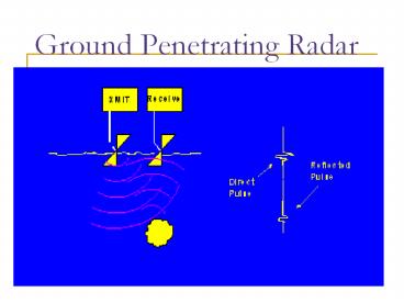
Title: Ground Penetrating Radar
1
Ground Penetrating Radar
2
Application
- Useful in Construction
- Prevent damage to underground lines
- Real-time data gives proximity to pipes
- Safety Conscious
3
Challenges
- Ground is very lossy medium
- Any moisture will absorb most of signal
- Requires more power than detection in air
- Power ? Pulse Width
- Low end of microwave regime used for detection
4
Pulse Width
- Pulse short enough to stop transmitting before
reflected signal returns to avoid interference - Pulse width Depth of Penetration / c , where c
is the speed of light - Depth of buried lines usually 2m
- Short pulse means less energy transmitted
5
Frequency Calculations
- Calculate Skin Depth to ensure most of the power
reaches the pipes - No greater than 2 meters
- ds sqrt(2 / (?µs) )
- µ µ0
- ssoil 1 to 10-4 S
- ? 2pf
6
Continued..
- Solve the skin depth formula for the frequency, f
633 MHz - Therefore, the low end of the range of
frequencies is 600 MHz - The high end was chosen to be 1000MHz to allow
better resolution
7
FMCW Radar
- Frequency Modulated Continuous Wave Radar (FMCW
Radar) - Key characteristic
- Allows a signal to simultaneously be transmitted
and received without interference - Benefit
- Pulse width can be increased -- no constraint on
when it must end
8
FMCW Radar
The Constant offset between the transmitted
signal (solid curve) and received signal (dashed
curve) is proportional to the distance from the
object
9
General Block Diagram - FMCW Radar
10
Frequency Modulator
- Modulating Signal
- Saw tooth from 600MHz to 1000MHz
- Carrier Signal
- Sine wave
- Frequency Modulated Signal
- Sine Wave with frequency varying linearly from
600MHz to 1000MHz
11
Voltage Controlled Oscillator
- Benefits
- Mobile, can be placed on machinery
- Vary frequency with Voltage input
- Issues
- High Frequency needed
- Tuning Diode
12
Circuit Design
13
Building Modulator
- Ordered Parts
- VCO (MN100EL1648 ON Semiconductors)
- Tuning Diode (MMBV609 ON Semiconductors)
- Create Printed Circuit Board
- Surface Mount Parts
- Solder Surface Mount Parts
- Build Complete Circuit
14
Providing Continuous Wave Capability
Power Divider
Transmit
Bandpass Filter
Mixer
LNA
Receive
Output Signal
15
Design
- Power Divider
- 3-port Device
- Output ports receive 85/15 Power Ratio
- Low Noise Amplifier
- Maxim2640 w/ frequency range 400MHz 2.5GHz
- Bandpass Filter
- Reject frequencies outside of 500MHz-1GHz
- Mixer
- Maxim2680 Down converter
- Output frequency range 10 500 MHz
16
Transmit / Receive Antennas
17
(No Transcript)
18
Antenna Design
- Bow-tie
- Operates over necessary range
- Simulation software available
- Possible to construct, test and tune within
allotted time and budget - Alternatives
- TEM Horn
- More control over directivity, but would be big
- Yagi Antenna
- More narrow beam, better for detection
19
Balun
- Importance
- Matches Impedance of antenna to impedance of line
- Minimizes VSWR which corresponds to a wide
bandwidth - Length needs to be a quarter wavelength
- At 750 MHz, ?/4 100 mm
- Length can be changed to get best impedance match
using the Smith Chart - Final Length 128.23 mm
20
Modulator Testing
- Use wire for 10 nH inductor
- Precision issue
- Tank Circuit Performance
- Tuning Diode less precise at lower Voltage input
- Use HP Spectrum Analyzer
- Detect Frequency output
- Lower frequency than desired
- 520MHz
21
Continuous Wave Testing
- Power Divider provided power to each arm, however
well below the desired levels - Bandpass Filter worked for a tighter band than
desired - Lack of power from power divider would not have
allowed mixer to operate properly
22
Theory/Reality
- First time design and build of this type of
circuit - Designed material ahead of class instruction
- Damaged a chip
- Power Divider not working as intended
- Bandpass Filter provides filtering but in a
tighter range than intended.
23
Power Divider
- Wilkinson Design instead of T-junction
- Use Resistor to Provide Isolation
- Multiple matching sections to provide broadband
matching
24
Bandpass Filter
- Design using Q-functions
- Q ?0 / Bandwidth
- Allows greater control over the response
characteristics - Applied to the stubs
25
Performance Verification of Antenna
- HP 8510 Network Analyzer
- Smith Chart to match antenna impedance to line
impedance - Change balun length to optimize VSWR
- Log Mag Plot to see that antenna resonates in the
desired range of frequencies
26
Transmit Antenna
27
Receive Antenna
28
(No Transcript)
29
(No Transcript)
30
Cost Analysis
- Frequency Modulator
- 15 for VCO
- 10 for Tuning Diode
- Filter, Amplifier, and Mixer
- 10 for etching solution
- Antenna
- 60 brass sheets
- 10 for Plexiglas, cables, etc.
- Salary
31
Improvements
- Inductor Capacitor tank with high Q-factor
- Use techniques learned in class to improve power
divider and bandpass filter - Simulate various antenna structures
- Take data for many scenarios with various antennas
32
References
- Online Resources
- http//www.georadar.com/howitwrk.htm
- http//www.ee.ucla.edu/students/archive/fredrick_m
s.pdf - http//www.tpub.com/neets/book12
- Books
- Surface Penetrating Radar by D.J. Daniels
- Microwave Engineering 2nd edition by David M.
Pozar. - Simon Haykins, Communication Systems. New York
John Willey Sons, Inc. 2001, 88-182
33
Thanks
- Professor Bernhard
- Professor Chew
- Professor Kudeki
- Professor Franke
- Judy Feng, EM graduate student
- Gentlemen in the Machine Shop
- Maxim Semiconductors
Recommended
