February, 07 PowerPoint PPT Presentation
1 / 12
Title: February, 07
1
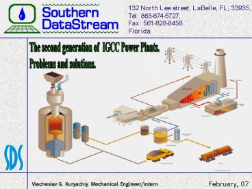
The second generation of IGCC Power
Plants. Problems and solutions.
Viacheslav G. Kuryachiy. Mechanical
Engineer/intern
February, 07
2
The basic technical issues of the problems and
improvements applied to the 2nd generation IGCC
Power Plants.
The research was prepared using the biggest IGCC
Power Plants ? Polk Power Station IGCC, 250
MWe. Tampa, Florida, USA. ? Wabash River
Coal Gasification Repowering Project, 262 MWe.
West Terre Haute, Indiana, USA. ? Demkolec
BV IGCC Power Plant, 250 MWe. Netherlands.
2
3
- Air Separation Unit
- The main air compressor deterioration
(output). - 30 of this loss is attributable to plaggage of
its after cooler and the resulting backpressure.
3
Failing / disadvantages
4
- Gasifier Unit
- The syngas scrubber evnironment is extremely
erosive and corrosive and leads to possible
gasifier outages. - Slag in the noncombustible mineral matter
contained in coal plus any of the coals carbon
which was not converted to syngas in the
gasification process. It can be unconverted
carbon which makes slag unsuitable for all known
applications. - Ash deposition on the second-stage gasifier
walls and downstream piping. - Failure of a refractory lined heat skirt below
the slagtap.
4
Failing / disadvantages
5
- Gas Cleaning Unit
- COS hydrolisis catalyst generates acid which
produces non-regenerable heat stable salts in the
acid gas removal solvent. The salts plated out
on the absorber trays and in downstream
equipment. - The upstream syngas scrubbers malfunction.
- Particulate breakthrough in the hot gas
barrier filter system primarily due to movement
and breakage of the ceramic candle filter
elements. - Chloride and metals poisoning of the COS
catalyst.
5
Failing / disadvantages
6
- Gas Turbine Unit
- Cracking in the gas turbine combustion
liners.
6
Failing / disadvantages
7
- Heat Recovery Steam Generator Unit
- Tube leakage in the heat recovery steam
generator. - Elemental sulfur deposit which formed in HRSG
economizer and in some higher temperature zones.
7
Failing / disadvantages
8
- Air Separation Unit
- Replacing the after cooler bundle and coating
all carbon steel parts. It prevents further
deterioration.
8
Solutions / improvements
9
- Gasifier Unit
- Ion exchange system installation.
- Doubling the size of the fines handling
system and installed additional slag handling
equipment to deal with the unconverted carbon
which is contained in the smaller slag particles
(the fines). - Using a less tenacious refractory in the
second-stage gasifier and changing the flow path
geometry and velocity. - Redesigning for future units to allow cooling
by a membrane wall. - Results
- - no refractory lining in gasification reactor
- - membrane wall is designed for life of reactor
- - no shutdowns for replacement or repairs.
9
Solutions / improvements
10
- Gas Cleaning Unit
- Utilizing the services of Union Carbide to
regenerate the solvent. - Installation of additional venturi scrubber
upstream of the - COS hydrolysis KO drum.
- Changing of ceramic candle filter elements on
improved metallic. A follow-on metallic candle
filter development - effort ensued using a hot gas slipstream, which
resulted in improved candle filter metallurgy,
blinding rates, and cleaning techniques. - Installation of a wet chloride scrubber
system and introduction of a different catalyst. - Installation of syngas moisturization block
to meet tightened NOx control requirements.
10
Solutions / improvements
11
- Gas Turbine Unit
- Replacement of the gas turbine fuel nozzles
and liners. - Improved Syngas Burner (Siemens)
- - use of 2 passages for syngas
- - optimal adaptation of nozzle design to
specific application.
11
Solutions / improvements
12
- Heat Recovery Steam Generator Unit
- Modifications to the HRSG to allow for more
tube expansion. - Elemental sulfur deposit which formed in HRSG
economizer - and in some higher temperature zones.
12
Solutions / improvements

