Microchannel for Dielectrophoretic Separation of Bioparticles - PowerPoint PPT Presentation
1 / 25
Title:
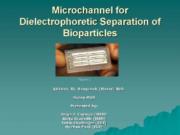
Microchannel for Dielectrophoretic Separation of Bioparticles
Description:
To fabricate a microchannel that uses Dielectrophoresis to separate bioparticles ... Fabrication (a) Glass Substrate with resist (b) Following expose and develop ... – PowerPoint PPT presentation
Number of Views:631
Avg rating:3.0/5.0
Title: Microchannel for Dielectrophoretic Separation of Bioparticles
1
Microchannel for Dielectrophoretic Separation of
Bioparticles
Figure 1
- Advisor Dr. Hongseok
(Moses) Noh - Group M19
- Presented by
- Jorge J. Capurro (MEM)
- Aisha Granville (MEM)
- Tuhin Chatterjee (ECE)
- HyeYun Park (ECE)
2
Problem Statement
- There is a need for inexpensive, portable and
more efficient devices to manipulate or separate
bioparticles.
- - Separation of tumor cells from blood sample
- Diagnosis of diseases such as Malaria
- Detection of bacteria such as Ecoli
- Separation of DNA molecules
- Identification and characterization of individual
cells - Entrapment of specific target molecules
Fig. 1a
3
Objective
- To fabricate a microchannel that uses
Dielectrophoresis to separate bioparticles
Figure 2
- Critical tasks
- - Understand Dielectrophoresis
- - Model both electrical field and fluid dynamics
- - Design (device, manufacturing process, and
mask) - - Fabrication using MEMS technology
- - Testing
4
Manipulation Techniques
There are some methods for particle separation
such as
- Optical tweezers
- Chromatography
- Field Flow Fractionation
- Electrophoresis
Video 1
5
Dielectrophoresis
- Dielectrophoresis is the motion of particles
induced by the polarization effects of a
non-uniform electric field.
Figure 3
Figure 4
Figure 5
Uniform electric field (DC, parallel electrode)
Non-uniform electric field (AC, interdigitated
electrode)
Non-uniform electric field (DC, pin/plate
electrod)
6
Dielectrophoresis(DEP)
Video 2
Video 3
Positive dielectrophoresis motion of particles
in the direction of applied field
Negative dielectrophoresis motion of particles
against the direction of applied field
7
Limitations
- Tribulations of using bioparticles during
modeling and testing - - Unsuitable environment for living cells
- - Theoretical results are not known
- Use of Polystyrene as opposed to bioparticle
- - Particle shape
- - Known dielectric properties
- - Environment
8
Organizational Chart and Deliverables
Theoretical study of DEP
Electric field analysis using Maxwell 2D
Electrical
Modeling
Mechanical
Fluid velocity distribution using ANSYS
Device
AutoCAD
Design
Manufacturing process
Microfabrication technique
Mask
AutoCAD
Electrode
Lift-off Process
Fabrication
Microchannel
SU-8
Packaging
Tubing
Testing
Visual Testing
9
Modeling
Medium Flow Direction
FDrag
FDEP
FDEP
FGrav
Figure 6
Eq. 3
Eq. 1
Eq. 4
Eq. 2
10
Electric Field Aspect
Thickness 1um, Width 1um, Gap 1um, Vp-p 2V
Graph 1
11
Electric Field
Different electrode arrangement
Thickness 0.1um, Width 1um, Gap 10um, Vp-p 2V
Graph 2
12
Electric Field
Dome-shaped electrode arrangement
Dome shaped geometry 10 um width, 105um
thickness, dome radius 5um, Vp-p 2V
Graph 3
13
Electrode configurations
DEP separation chamber
Figure 7
14
Fluid Mechanics Aspect
- Effects of channel geometries
- Effects of electrode arrangements and geometries
Medium Flow Direction
(a)
(b)
Figure 8 - Top View
(a)
(b)
(c)
(d)
Figure 9 - Side View
15
Device Design
Medium Inlet
Medium Outlet
Electrodes
Sample Injection
Rubber Septum
Substrate
Screw
(b) Side View
(a) Top View
Figure 10
16
Fabrication
(a) Glass Substrate with resist
(e) Pattern SU-8
(b) Following expose and develop
(f) Apply Substrate
- MEMS
- Electrode Thickness
- PDMS
(c) Deposition of Ti/Au
(d) Lift-off
Figure 11
17
Packaging Fabrication
- Polymer Tubing and gold wires
- Drilling
- Diamond Mandrel
Holes
Tubing
Figure 12
Electrode Wiring
18
Testing
- Individual solution
- Mixture of solution
- Visual Testing
Figure 13
19
Gantt Chart
20
Budget
- Software
- - Maxwell 2D
- - ANSYS FOLTRAN
- Materials
- - Glass wafers 400
- - Masks 300
- - Cleanroom supply 200
- - Polystyrene particles 200
- - Chemicals 200
- - Miscelleneous 200
- Total
1,500 - Equipments
- - Mask aligner, spinner, hot plate, oven
(cleanroom) - - Mechanical drill, hot press (MEM)
- - Microscope, syringe pump, function generator
(Dr.Nohs lab.)
21
Social Impact
- Generate more interest in Bio-Particle separation
research field - Contributing to solutions for current biomedical
problems
22
Conclusion
- Electrode arrangement and channel geometries
affect abilities to separate bio-particles. - Continue to
- - Model
- - Design
- - Fabricate
- - Find maximum parameters of bioparticles.
Future Work
23
References
- Figures
- http//www.dielectrophoresis.org/PagesSubordinate/
MicroDev.htm - http//www.me.gatech.edu/memslab/moses.html
- http//www.ibmm-microtech.co.uk/pages/science/dep.
htm - http//www.dielectrophoresis.org/PagesSubordinate/
MicroDev.htm - 5. Frenea M et al, Design of Biochip
microelectrode arrays for cell arrangement,
pg140, 2nd ann Int IEEE-EMBS spec topic conf on
Microtechnologies in Med Bio, May 2002 - Videos
- 1. http
- 2. http//www.dielectrophoresis.org
- 3. http//www.dielectrophoresis.org
- Equations
- 1. Chan Ka Lok et al, Cellular Characterization
and Separation Dielectrophoretically activated
cell-sorting, pg2953, Proc 20th ann int conf
IEEE Engg in Med Bio society Vol 20, no. 6, 1998
24
Acknowledgements
- Dr. Hongseok (Moses) Noh
- Kamat Mahesh Keshav
- Dr. Bakhtier Farouk
25
QA

