Wireless Sensor Networks - PowerPoint PPT Presentation
1 / 37
Title:
Wireless Sensor Networks
Description:
Interface with Base Station MIB500CA Mote Interface Board. Objective (cont. ... The cost of components for each mote will not exceed $41. Cost of Manufacture ... – PowerPoint PPT presentation
Number of Views:531
Avg rating:3.0/5.0
Title: Wireless Sensor Networks
1
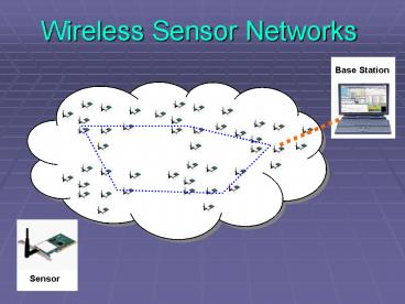
Wireless Sensor Networks
Base Station
Sensor
2
Hardware Design Testing
Software / Firmware Design Testing
Documentation
Team Members
Sensor Antenna Interface
Tiny OS Research
Microsoft Project Deliverables
Leader Thomas Butler
Power Supply
Communications Simulation Research
Meeting Minutes Deliverables
Kelly Lancaster
Power Supply DC to DC Converter
Research
Meeting Minutes Deliverables
Michael Middleton
Microcontroller Interface
Porting TinyOS Application Design
Webpage Design Deliverables
Kennabec Walp
The Lazz
Dr. Georgios Lazarou Advisor
3
Abstract
- Wireless Sensor Networks
- Hot Research Topic
- Distributed Sensing
- Mississippi State University Initiative
4
Motivation
- Collecting Interpreting Data
- Various environmental changes
- Tracking
- Tracking a group of military soldiers
- Monitoring movement or activity within a building
5
Problem Statement
- Wired Sensors are Impractical
- Wires add to total cost
- Difficult to use discreetly
- Cannot be used on rotating objects
- Existing WSNs
- Power Efficiency
- No error correction / channel reliability
- Integration could be improved
- Scalability
- Network should function with 2 or 2000 nodes
6
Objective
- To develop a module that is part of a large-scale
wireless sensor network that works reliably while
unattended. - Small, Reliable, and Efficient
- Communicate with Other Sensor Modules Over a
Given Area - Interface with Base Station MIB500CA Mote
Interface Board
7
Objective (cont.)
- Improve Power Efficiency
- Channel Coding
- Improve Reliability
- Decrease of Retransmissions
- High Integration (MCU TxRx Single Chip)
8
Features
- TinyOS
- Unprecedented Communications and Processing
- 6 Mo. Battery Life
- 3V 1000mAh Coin Cell Battery
- Self-Organizing Network
- Various Sensing Capabilities
- Light, Temperature, Barometric Pressure,
Acceleration, Acoustic, Magnetic, etc.
University of California at Berkeley
9
TinyOS
- Open Source Modular Runtime Environment
- Designed for Embedded Systems
- Concurrency-Intensive Applications
- Minimal Hardware Resources
- Ad hoc Multi-Hop Routing
- Runtime Power Management
10
Hardware Block Diagram
Transceiver
- Chipcon CC1000
- Low Power Consumption
- Rx 9.1mA
- Tx 5.3 - 26.6mA
- Long Transmission Distance
- Max 350m
- Small Package
- 12mm x 12mm x 1.2mm
11
Transceiver
- Chipcon CC1000
- FSK modulation
- Transmit distance 350m
- Frequency programmable
- RFM TR1000
- OOK ASK modulation
- Transmit distance 120m
- Frequency set
RFM TR1000
12
Other Transceivers Considered
13
Hardware Block Diagram
Processor
- 8051
- Low Power Consumption
- Separate Idle Modes and Sleep Modes
- Well-Established Microcontroller Architecture
- CC1010
- CC1000 8051 on Single Chip
- 3 MHz Clock
14
Processor
- Chipcon CC1010 (8051)
- Atmel Atmega 128L
15
CC1010 Size Comparison
CC1010 1.44cm2
Our Design
MICA2DOT
16
Processor
- CC1010
- CC1000 Transceiver 8051 MCU integrated
- Reduce Overall Size
- Improve Power Efficiency
- Decrease Interference by Eliminating Exposed
Channels
17
Hardware Block Diagram
Power Supply
- 3.3V, 60mA Regulated Supply
- 3V, 1000mAh Coin Cell Battery
- DC-DC Converter
18
Hardware Block Diagram
Sensor Interface
- 21 Pins
- 6 Analog I/O
- 6 Digital I/O
- 6 UART
- 2 Gnd, 1 Power
- Spaced Around Circumference of Mote
- Pin-Compatible With Industry Standard Mica2Dot
Motes
19
Software User Interface
20
Network Allocation
21
Data Transfer
22
Data Flow DiagramSunny Day
23
Hardware Testing
- Tested RFICs
- Development Kit
- Simple Temperature Sensing / Data Transmission
Demo
24
Cost of Manufacture in Quantity
- CC1010 transceiver/microcontroller 10.00
- RH 433MHz ¼ wave monopole antenna 8.00
- 3V 1000mAh coin cell battery 4.00
- Coin cell battery holder 0.36
- 3V 30mA DC-DC converter 2.50
- LED (3) 3.00
- PCB Fabrication 6.00
- Miscellaneous Components lt 5.00
- The cost of components for each mote will not
exceed 41.
25
Cost of Manufacture Prototypes (2)
- CC1010 Development Kit 650.00
- (2 evaluation modules, 2 antennas, programming
- board, development software, 5 sample chips)
- 3V 1000mAh coin cell battery (2) 8.00
- Coin cell battery holder (2) 1.00
- 3V 30mA DC-DC converter (2) 5.00
- LED (6) 6.00
- Miscellaneous Components lt10.00
- Total cost to prototype will be about 680.
26
Timeline
27
What is Left to Be Done?
- Firmware Design
- Port TinyOS to CC1010
- Add Channel Coding to Link Layer
- Develop Sensing / Transmission Application
- Software Design
- Base Station Interface via RS-232
- Graphical Visualization
- Network Status Visualization
28
What is Left to Be Done?
- Simulation
- How Much Does Channel Coding Improve Power
Efficiency? - Meet BER Constraint
- Meet Power Constraints
- Testing
- Actual Battery Life vs. Advertised Battery Life
- Transmission Distance (Indoor / Outdoor)
29
Design I Goals
- Working Prototype
- Communication Between Two Modules
- Interface Sensor
- Transmit Data to Base Station
- Plan for Meeting Size Constraint
30
Design II Goals
- Scalable Network of Motes
- Mote Meeting our Design Constraints
- Small
- Reliable Transmission
- Power Efficient
31
Summary
- Design a Wireless Sensor Network Module
- Improve Power Efficiency through
- Channel Coding
- Integration of Microcontroller and Transceiver
- Wide Range
- Long Lifetime
32
Questions
- ?
33
Resources Needed
- Hardware
- CC1010 Development Kit (433 MHz tuned)
- Oscilloscope
- Spectrum Analyzer
- Software
- PSpice
- SystemView
34
References
- Tire Pressure Monitoring An Industry Under
Pressure, Sensors Magazine, July 2003
35
Software Flow Chart
- OS
- Layer Stack
36
State Machine Diagram
37
Simulation


