Notes 6 - PowerPoint PPT Presentation
1 / 35
Title:
Notes 6
Description:
... Green's function is the Fourier transform of the spatial-domain Green's function: From the convolution property of Fourier transforms: 13. Patch Fields (cont. ... – PowerPoint PPT presentation
Number of Views:47
Avg rating:3.0/5.0
Title: Notes 6
1
ECE 6345
Fall 2006
Prof. David R. Jackson ECE Dept.
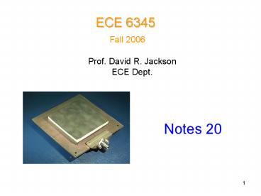
Notes 20
2
Overview
In this set of notes we apply the SDI method to
find the field of a finite current sheet.
- Start with the field produced by an infinite
phased current sheet (derived in Notes 19). - Apply superposition to find the field of the
finite current sheet (Fourier integral). - Identify a closed-form expression for the Fourier
transform of the field. - Identify a TEN model where voltage and current
now represent the Fourier transform of the field
quantities. - As an example, calculate the field due to a
rectangular patch on top of a substrate.
3
Finite Source
For the infinite current sheet we have
This produces a field
Note the i subscript on the voltage functions
denotes the voltage due to a one-Amp parallel
current source.
where
4
Finite Source (cont.)
Recall that
Hence
where
5
Finite Source (cont.)
Adding the contributions from all the phased
current sheets, we have
Taking the limit as
6
Finite Source (cont.)
From this we can identify
or
From this we can make the following TEN
identifications
7
TEN
The TEN models are shown below.
8
Patch Fields
Find Ex (x,y,0)
9
Patch Fields (cont.)
10
Patch Fields (cont.)
11
Patch Fields (cont.)
Define
Then
Also, we can write
12
Patch Fields (cont.)
The spectral-domain Greens function is the
Fourier transform of the spatial-domain Greens
function
From the convolution property of Fourier
transforms
13
Patch Fields (cont.)
Note more generally,
TEN
T TM or TE
14
Patch Fields (cont.)
From the TEN we have
15
Patch Fields (cont.)
Define the denominator term as
so that
16
Patch Fields (cont.)
We then have
The final form of the electric field at the
interface is then
17
Polar Coordinates
Use the following change of variables
18
Polar Coordinates (cont.)
Using
we have
This is in the following general form
19
Poles
Poles occur when the either of the following
conditions are satisfied
TMz
20
Poles (cont.)
This coincides with the well-known Transverse
Resonance Equation (TRE) for determining the
characteristic equation of a guided mode.
(Kirchhoffs laws)
Hence
so that
21
Poles (cont.)
Comparison
TRE (surface-wave mode)
Poles
(A similar comparison holds for the TE case)
22
Poles (cont.)
Hence, we have the conclusion that
That is, the poles are located at the wavenumbers
of the guided modes (the surface-wave modes).
23
Poles (cont.)
The complex plane thus has poles on the real axis
at the wavenumbers of the surface waves.
24
Path of Integration
The path avoids the poles by going above them.
lossy case
This path may be used for numerical computation.
lossy case
25
Path of Integration (cont.)
The path avoids the poles by going above them.
lossless case
Practical note If hR is too small, we are too
close to the pole. If hR is too large, there is
too much round-off error due to exponential
growth in the sin and cos functions.
(typical choices)
26
Branch Points
To explain why we have branch points, consider
the TM function
with
If
changes
27
Branch Points (cont.)
Note the representation of the square root of 1
as j is arbitrary here.
28
Branch Points (cont.)
Branch cuts are necessary to prevent the angles
from changing by 2?
Note the shape of the branch cuts is arbitrary,
but vertical cuts are shown here.
29
Branch Points (cont.)
We obtain the correct signs for kz0 if we choose
the following principal branches
30
Branch Points (cont.)
The wavenumber kz0 is then uniquely defined
everywhere in the complex plane
31
Riemann Surface
The Riemann surface is a pair of complex planes,
connected by ramps (where the branch cuts used
to be). The angles change continuously over the
surface. All possible values of the wavenumber
are found on the surface.
Example
top sheet
bottom sheet
32
Riemann Surface (cont.)
Riemann surface for z 1/2
top sheet
bottom sheet
Note a horizontal branch cut has been
arbitrarily chosen.
33
Riemann Surface (cont.)
Riemann surface for z 1/2
34
Sommerfeld Branch Cuts
Sommerfeld branch cuts are a convenient choice
for theoretical purposes (discussed more in ECE
6341)
on branch cut
35
Complex Plane

