Base Design 212007 PowerPoint PPT Presentation
1 / 8
Title: Base Design 212007
1
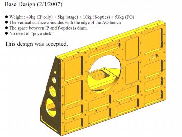
Base Design (2/1/2007)
- Weight 49kg (IP only) 5kg (stage) 10kg
(f-optics) 53kg (FO) - The vertical surface coincides with the edge of
the AO bench - The space between IP and f-optics is 6mm.
- No need of pogo stick
This design was accepted.
2
Additionally needed features
3
Aluminum bars
Tapped holes are necessary at least at the
positions shown in the figures (Dimensions are
not specified, so you can decide).
Front surfaces of the aluminum bars coincide with
that of IP.
Tapped hole (M6, not through)
4
Aluminum cover
Aluminum cover. Height of the cover and the
screws should not exceed 10 mm from IP surface.
5
Platform for AO alignment
- AO group needs a platform on which they can put
an alignment target and an IR camera. - The vertical plate is same as the one used in
Foreoptics. (i.e.The positioning mechanism is
same as Foreoptics)
0
75
Tapped hole (M6)
250
Dimension of this (horizontal) plate should be
accurate
425
Vertical plate
AO will put something like this
125
125
100
500
6
Definition of Nasmyth focal plane
- AO group wants to define the Nasmyth focal plane
with mechanical accuracy (0.1mm, 1arcmin) - They put a piece of paper with cross lines on
the mechanically defined focal plane, and adjust
the last mirror so that the laser beam hits the
cross lines. - Position of the focal plane and the interface
surface relative to the pins should be
mechanically accurate (0.1mm, 1arcmin). - Positions of the pins will be provided by AO
group, once IP design is fixed.
Last mirror
Pins
Optical axis (Laser)
Nasmyth focal plane (paper with cross lines)
Interface surface
7
F-conversion optics
- Three fixed pins are necessary somewhere on the
bottom plate. - Three adjustable pins are also necessary at the
positions shown in the figure. - The cover is necessary all the time on the top
plate. IP side can be open because of a tight
space. - The handles are necessary all the time on the
top plate. - The adjustable pins can be adjusted with the
cover and the handles attached. - The bottom plate is permanently fixed on the
stage. - The adopter plate is permanently fixed under the
stage. - Top plate is detachable from the bottom plate.
- The adopter plate is detachable from the IP.
- Position of the f-conversion optics relative to
the pins in the previous slide should be
mechanically accurate and repeatable.
Adjustable pins
Adaptor plate
cover
Handles
Top plate
Bottom plate
Linear stage
8
Kyoto-3D compensator
Requirement will be coming soon

